Keywords
|
| Fault-tolerant systems, Self-repair, Stem cells, Differentiation, Field programmable gate array |
INTRODUCTION
|
| Electronic systems have provided the tools enabling the rapid processing and interpretation of information, which in turn has made a dramatic impact on our ability to communicate, control physical systems and understand the world around us. With VLSI chip transistors getting smaller and smaller, today's digital systems are more complex than ever before. The greater complexity and increased levels of circuit integration, lead to the rise of device transistor counts and smaller feature size. This increased complexity leads to more cross-talk, noise, and other sources of transient errors during normal operation. Thus reliability becomes an increasingly difficult problem. For systems operating in harsh and/or hostile environments, such as satellites, aircrafts, nuclear reactor control systems, even a single failure event can result in huge loss and disastrous effects. Faults are unavoidable and they occur in any electronic system no matter how much care is taken in designing and building it. And with critical applications relying on faster and more powerful chips, fault-tolerant and self-checking mechanisms must be built in to assure reliable operation. |
| In general, fault tolerance systems does not guarantee the reduction of cost and also with the amount of circuitry involved considerably increases the probability of faults. Introducing fault tolerance in single VLSI chips in general, and FPGAs in particular, has therefore been considered too expensive to be commercially viable. This outlook, however, appears to be changing. As circuits in generals, and FPGAs in particular, become more complex, their yield i.e., the percentage of chips which exit the fabrication process without faults, is decreasing and chip manufacturers are becoming more and more interested in being able to produce chips capable of operating in the presence of faults. FPGAs are ideally suited for this kind of approach, as their regular structure allows for the possibility of reconfiguration, and some of the leading manufacturers are beginning to seriously consider the option of introducing fault tolerance in their circuits. Self-repair is a technique which achieves fault tolerance with a somewhat different approach. Rather than extracting the correct result from a faulty but redundant output, it aims at producing the correct output by removing the fault from the circuit. Since current technology does not allow the fault to be removed physically, self-repair relies on a reconfiguration of the circuit which reroutes the signals so as to avoid the faulty areas. This technique, while often capable of achieving considerable fault tolerance, with a relatively small amount of additional logic, is obviously more complex to implement, as it requires both the ability of identifying the exact location of a fault in the circuit and the presence of redundant logic capable of replacing the functionality of the faulty part of the circuit. These systems work in different way, where a faulty element can be replaced by a spare which, being identical, can take over its functionality. |
RELATED WORK
|
| During the early stages of the development of fault-tolerant systems, dual modular redundancy (DMR) and triple modular redundancy (TMR) methods were introduced [1]. These techniques ran the same modules in parallel, and thus a faulty module could be distinguished by comparing outputs of the same modules and voting for the majority one (with TMR) or by using an additional device (with DMR). However, these methods have several problems. The size of the module is so huge that a large part of the circuit must be replaced even if a small part in the module is malfunctioning. Furthermore, redundancy has to be running all the time, and it can only cover the fault once. |
| The self-healing architecture proposed by P.K.Lala [5], capable of self-repairing, was inspired by the human immune system. All cells in the architecture are programmable, so when any functional cell goes faulty, a suitable spare cell is selected and the inputs of the faulty functional cell are transferred as inputs to the selected spare cell. Another such system called Unitronics is an artificial bio-inspired prokaryotic array based system that proposes a multi-layered hierarchical architecture [6], [14]. It is an on-line self-repairing system that has a low overhead by introducing a new method for configuration memory reduction. The popular self-repairing system called MUXTREE [7], [11] is a digital circuit which is converted into an array of cells and the initial connection information among the cells are encoded as a gene in each cell. These elements are themselves capable of self-test and self-repair. Embryology and Electronics combined to form a new field called Embryonics, which provided the base for the self-repairing systems [12]. As the biological cells carry the genetic code of the whole system and are differentiated according to the location of the cell in the system, an embryonic self-repairing circuit is organized with building blocks that have identical structures and that vary according to the expressed genetic code in each block [3], [8]. These self-repairing circuits can also recover from a fault by isolating the faulty block and differentiating a spare (stem) block with the same genetic code previously held by the faulty block [16]. |
SYSTEM MODEL
|
| Among the various methods of cell-to-cell communication in our body, endocrine cellular communication is particularly interesting. Basically, an endocrine cell releases a hormone from the signaling endocrine cell, and the hormone flows through the blood vessel until it binds to the target cell. Although the blood contains various hormones, only the receptor on the target cell receives the selected hormone. The special method of endocrine cellular communication is based on a specific endocrine cell that secretes a hormone only if it receives another hormone from another endocrine cell. The blood vessel delivers the hormones between cells. When a functioning endocrine cell dies through apoptosis, the special endocrine cellular communication maintains hormone delivery by differentiating a stem cell into a cell having the same genome part as that of the dead cell. Thus, in addition to its own functioning, the genome in the endocrine cell has the information about connections between cells. The inspiration obtained from the biological endocrine system lies in the efficient and flexible communication mechanism between endocrine cells. In the endocrine system, the information between endocrine cells is exchanged via the hormones, and this forms a complex communication network. The structure of this network is flexible and easily changed by choosing and adjusting the hormones to be used for secretion and reception in each endocrine cell. Even if an endocrine cell dies through apoptosis, a new endocrine cell having the same function of the dead cell is produced by differentiation and the overall communication network is recovered [2]. |
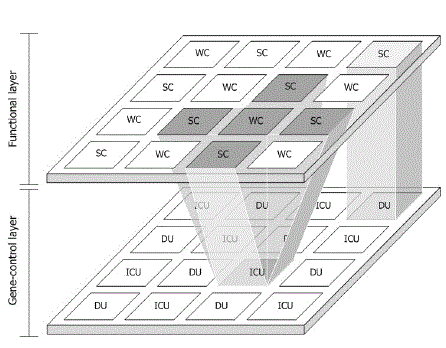
| By adopting a similar mechanism of endocrine cellular communication in an electronic circuit [4], [9] a novel wiring architecture are devised, that can maintain the function as well as connections by replacing the faulty module with a spare module without any additional rerouting process, thus simplifying the self-repairing mechanism [10]. The architecture is composed of a functional layer and a gene-control layer as shown in fig.1. In the functional layer, the circuit is divided into LUT-based modules. Encoded data in each module are composed of both functional and connection data. Therefore, the function and connections of the whole system are maintained by simply expressing the same encoded data to the spare (stem) module, while the wiring architecture connects correctly after the encoded data are properly assigned to the spare module. Each WC is surrounded by four adjacent spare cells in North/Top, South/Down, East/Right and West/Left. The fault signal is generated in the functional layer and then reaches the genecontrol layer, which determines the spare module in the functional layer that will take the faulty module instead. The main role of the gene-control layer is to assign the correct spare module to replace the faulty one. In addition, modules involved in this mechanism are distributed and operated in parallel. Therefore, even if several faults occur simultaneously in different modules, the system can recover them. Furthermore, it can preserve the state and function that existed just before the fault occurred in the sequential system. |
FUNCTIONAL LAYER
|
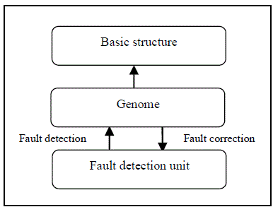
| The functional layer consists of working cells also known as functional cells, and the spare cells. The working cells and spare cells are similar in architecture. The only difference among them is the encoded data (genome) stored in them, which contains their functionality and interconnection details. The main components of a working cell are shown in fig.2. |
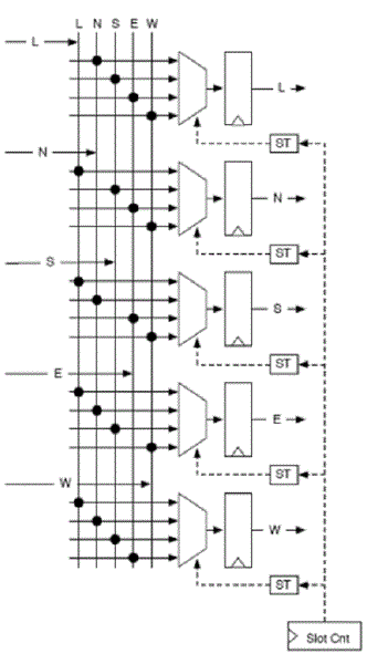
| The basic structure of the functional cell performs the operations of the desired application. It operates on the basis of the LUT, the MUX, and the DEMUX. It also has a D-type flip-flop for the sequential operation. Each cell has connections to the adjacent cells and to distant cells. The output of the cell can also be transmitted for a distant connection. In order to transfer the data stream between the working cells and the spare cells, a reliable routing architecture must be build. The data is transmitted with the help of in built router in the functional cell. The routing architecture is composed of connection wires and input selection MUXs in order to dynamically connect the output of a working cell or its spare cells to the input of another working cell or its spare cells. These connections among inputs and the outputs of the cells are controlled by the genome of each cell. It performs calculations, to find out the exact direction in which the data should be transmitted. The basic design of the MUXs for routing is shown in fig.3. Each MUX is connected to four inputs. The black dots represent a connection point. ST represents the schedule table for each multiplexer. It is used to schedule the operation sequence or time based on the type of operation. A slot counter drives the schedule table and it is incremented for each data forwarded. |
| The whole application system operates with the assembly of WCs and the operation of each cell is based on the genome, the genome plays the most important role in the cell. Genome is the like a memory, which stores the whole functionality of the working cell and their interconnections with other working cells. The genomes of every WC are stored in the other memory space also. The whole genome is transferred to the spare cell if a fault arises. The genome of the artificial endocrine cell is implemented in the form of a configuration register. The applications into which the FPGA system can be embedded are exposed to radiation constantly and the radiation causes a voltage spike and switches the data between “0” and “1” as a transient error. The fault detection is performed by generating even parity bits for the genome and then comparing them. If fault is detected then the position of the faulty bit is found by comparing the genome bits with the complement bits of the original genome value. Then the faulty bit is alone flipped (i.e.) 0 to 1 or 1 to 0. Sometimes the location of the faulty bit cannot be identified. In such cases, the entire genome value will be replaced by the normal genome from the encoded data. This method of fault detection and correction can cover upto 3 bits simultaneously. If the fault appears simultaneously, even after fault correction and genome replacement, then it is said to be permanent fault and the entire cell has to be replaced. The available spare cell is calculated and the genome is transferred to the particular spare cell. Then the spare cell takes the functionality of the faulty working cell. The following shows the algorithm of the fault detection unit. |
| Step1: Check the genome for fault by generating even parity bits. |
| Step2: If fault is detected, check whether the same fault has occurred consecutively, else normal operation is continued. |
| Step3: Then check the genome again for fault. If fault still exists then it is considered as permanent fault and cell replacement is done. |
| Step4: If the fault has not occurred consecutively, then it is considered as transient fault and can be corrected. |
| Step5: The location of the faulty bit is found by comparing the genome with its compliment and then flipped to ‘0’ or ‘1’. |
| Step6: After correction of the faulty genome, once again it is checked for fault and if no fault exists normal operation continues. |
GENE CONTROL LAYER
|
| The gene-control layer is functionally positioned in parallel with the functional layer and it consists of two units. The Index Changing Unit (ICU) which takes in charge of a WC and its four neighbouring SCs and the Differentiation Unit (DU) which is assigned for every SC. In case of permanent fault, the fault signal is sent to the ICU. When the ICU receives the fault signal, it checks for the spare cell in anti-clockwise direction, starting from the left. In order to control the cell replacement, index bits are used which are changed corresponding to the available spare cell and indicates to the DU, that the spare cell is ready to replace the function of the faulty cell. Index bits comprise of three types of bits: state bit, differentiation bit and direction bits as shown in Table 1. |
| Initially these bits are set to ‘0’. The state bit indicates whether the cell is a working cell or a spare cell. The direction bits signify the direction in which the genome must be sent, to convert the spare cell in that particular direction, into a working cell. One ICU is responsible for changing the index bits in four neighbouring SCs of the WC. When all the spare cells corresponding to a working cell is used and there are no more spare cells for fault recovery, the system stops operating and moves on to system failure. Every spare cell has a DU that differentiates the spare cell referring to the differentiation bit and the direction bits. If the differentiation bit of the spare cell is changed to “1” while having the direction bits of “10,” the spare cell is differentiated into a cell like the WC, which is located on the right side. After differentiation of the spare cell is over, the DU changes the differentiation bit. The entire process will be repeated if faults occur in any of the working cells. |
COMPARISON WITH OTHER ARCHITECTURES
|
| The architecture of the self-repairing system is compared with the self-healing system, the MUXTREE system and the TMR approach in terms of additional hardware for re-routing, unutilized resources, simultaneous fault coverage and functional fault coverage. From the comparison, the architecture of self-repairing system is found superior to the other architectures of fault-tolerant systems. |
| A. Additional Hardware for Re-routing |
| The main disadvantage is of the existing approaches is that; they require additional hardware for the rerouting after the replacement of a cell. The self-healing approach has a router cell that helps the system bypass a faulty cell after replacement of a cell [5]. The MUXTREE approach has additional MUXs and DEMUXs for the rerouting process after the replacement of a cell. Each cell has MUXs and DEMUXs, which can bypass vertical and horizontal signals by changing the selection bits [7]. But the self-repairing system does not require such additional hardware for the rerouting process after the replacement of a cell, because the replacement of the cell also accompanies the necessary rerouting through the DEMUX. |
| B. Unutilized Resources |
| An unutilized resource is the maximum number of working molecules that are unutilized and disposed off due to the non-availability of spare molecules in the cell, even though the molecules are not faulty. This happens majorly in the MUXTREE system. If a fault occurs in a functional molecule that has no more spare molecules for replacement, the cell consisting of those molecules is replaced by a spare cell. In this case, other normal operating molecules and unutilized spare molecules are disposed off [7]. The unutilized resource of the TMR system is equal to the number of functional cells, because one of two redundancies is useless after a fault occurs in the functional cell and one redundancy is being used [1]. On the other hand, the self-repairing system and the self-healing system do not have unutilized resources. From the above discussions, the architecture of self-repairing system is found superior to the other architectures of fault-tolerant systems, in terms of additional hardware used for re-routing and unutilized resources. |
| C. Simultaneous fault coverage |
| Simultaneous fault coverage is the maximum number of faults that occur at the same time and can be recovered in the system. The three systems, except the MUXTREE system, can recover simultaneous faults as long as the number of faults does not exceed that of the spare cells. |
| D. Functional fault coverage |
| Functional fault coverage is the maximum number of faults that can be tolerated for one functional cell. One functional cell in the proposed system can be recovered four times and that in the MUXTREE system can be recovered as many times as the number of columns of SC. On the other hand, the functional cell in the self-healing system and the TMR system can tolerate only one since such systems cannot use another spare cell and redundancy after it is recovered once. |
SIMULATION AND RESULTS
|
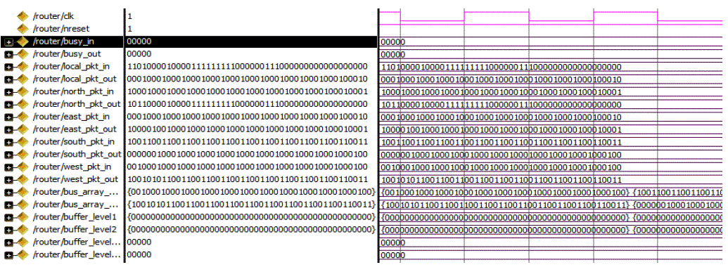
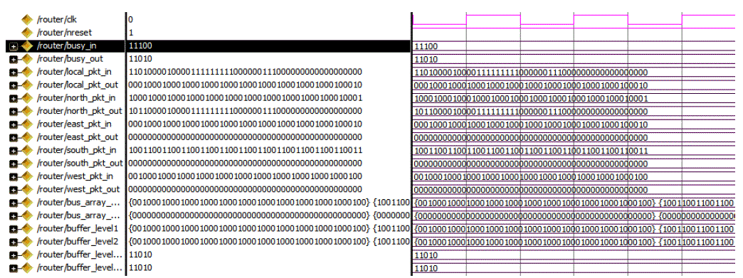
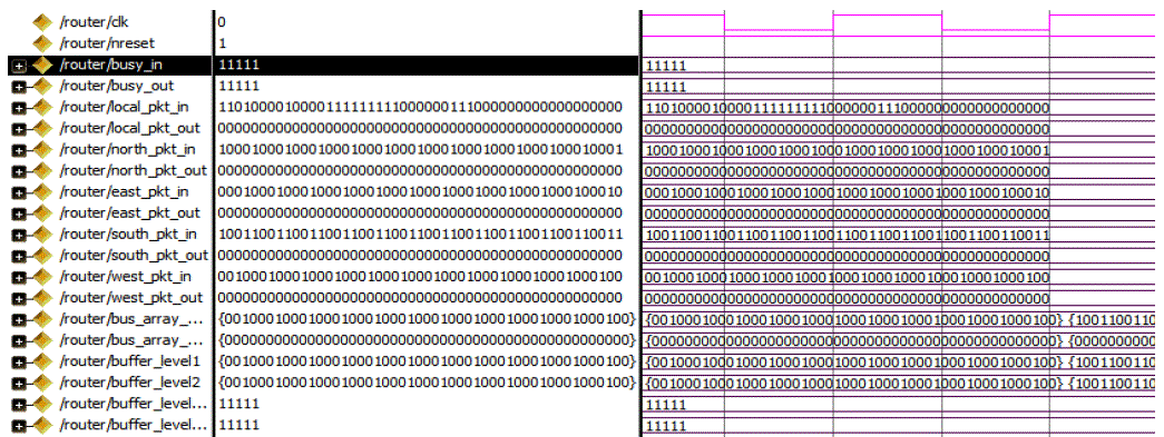
| In order to implement the concept of routing in a working cell, the algorithm written in VHDL for a working cell to route to any one of the adjacent spare cells is simulated using Modelsim SE PLUS 6.5. The model describes the input and output signals in all directions (i.e.) local, north, east, south and west directions. The 49 bit data consist of actual data, x and y counter, collision flag, busy and 2 level buffers. The x and y counter indicates the direction bits. The y counter is given priority than x counter and the negative flag associated with the counter is checked as shown in table 2. The two buffers are used to hold the data when there is collision. After finding the desired direction for each input, the chances of two or more data heading towards the same direction are found and if so the collision flag is set to 1. Then the corresponding colliding data is placed in any of the free buffers and the respective buffer level used is set to 1, so that the incoming data will be suspended for some time until the collision is cleared. Also the immediate data from the collision direction is stored in the second buffer and its used signal is raised to 1. The busy_in signal is the input signal given to indicate which direction cells are busy. The busy_out is the output signal which is determined by the inputs given. The busy output signal is also sent in order to indicate that the router is busy and it cannot accept any data at that time. If data is sent by the collision direction cell, irrespective of the busy_out signal, then the data will be lost. The following simulation outputs depict how each input data (i.e.) local, north, east, west and south, is routed to its destination based on the input busy signal and collision flag. |
| The output shown in Fig. 5 shows the response of the system when there are no input busy signals and fault in the data, so the chances of collision are very less. After finding the desired direction for each input, with respect to the counter bits and collision flag, the local_pkt_in is forwarded to north_pkt_out, north_pkt_in is forwarded to east_pkt_out, east_pkt_in is forwarded to local_pkt_out, south_pkt_in is forwarded to west_pkt_out, and west_pkt_in is forwarded to south_pkt_out. Here there is no collision in terms of busy signals and routing of different data to same direction. So buffer levels 1 and 2 are not used and busy_out is all set to 0. |
| The response of the system when there is fault and busy signal is in 3 directions is shown in Fig. 6. Here the input busy is given for east, south and west directions. So the north_pkt_in which has to be forwarded to the east_pkt_out, the west_pkt_in which has to be forwarded to the south_pkt_out and south_pkt_in which has to be forwarded to the west_pkt_out are stored in the buffer1. Then the immediate data following those in the buffer is accepted and stored in buffer 2. |
| The response of the system when busy_in is given in local, north, east, south and west directions is shown in Fig. 7. The east_pkt_in, local_pkt_in, north_pkt_in, west_pkt_in and south_pkt_in are stored in buffer and busy_out is set for all the directions since both the buffers are full in all the directions. |
CONCLUSION
|
| A self-repairing digital system inspired by endocrine cellular communication is presented in this paper. The architecture for the routing the cell in the functional layer was developed and well organized such that rerouting between neighbouring cells after the replacement of a faulty cell can be done without the use of additional hardware. Furthermore, the cells could be arranged in a flexible manner such that the WC could be expanded to any four directions. Also this self-repairing system was compared with other major self-repair approaches and it was found that the proposed system have low overhead, and no unutilized resources for fault recovery. For further improvement of the proposed self-repairing system, there remain several issues awaiting further studies. When the number of fault rises, the number of busy signal also rises. This will cause the routing of genome to delay, in case of permanent fault. Hence the synchronous nature of the system will get affected. So in order to preserve the synchronous logic, clock distribution network concept can be used, to make the system a fast self-repairing digital system. The power consumption also can be reduced by using clock gating. |
Tables at a glance
|
 |
| Table 1 |
|
Figures at a glance
|
 |
 |
 |
| Figure 1 |
Figure 2 |
Figure 3 |
 |
 |
 |
| Figure 4 |
Figure 5 |
Figure 6 |
|
References
|
- W. C. Carter, “Fault-tolerant computing: An introduction and a viewpoint,” IEEE Trans. Comput., vol. 22, no. 3, pp. 225–229, Mar. 1973
- B. Alberts, A. Johnson, J. Lewis, M. Raff, and K. Roberts, Molecular Biology of the Cell., pp. 880–883.487–490, New York: Garland, 2007.
- C.Ortega and A. Tyrrell, “Design of a basic cell to construct embryonic arrays,” IEE Proc. Comput. Digital Tech., vol. 145, no. 3, pp. 242–248, May 1998.
- A. J. Greensted and A. M. Tyrrell, “An endocrinologic-inspired hardware implementation of a multicellular system,” in Proc. NASA/DoDConf. Evolvable Hardw., pp. 245–252, 2004.
- P. K. Lala and B. K. Kumar, “An architecture for self-healing digital systems,” J. Electron. Testing: Theory Appl., vol. 19, no. 5, pp. 523–535, Oct. 2003.
- M. Samie, G. Dragffy, and T. Pipe, “UNITRONICS: A novel bioinspired fault tolerant cellular system,” in Proc. NASA/ESA Conf. Adapt.Hardw. Syst., pp. 58–65, Jun. 2011.
- G. Tempesti, “A self-repairing multiplexer-based FPGA inspired by biological processes,” Ph.D. dissertation, Dept. Comput. Eng., Princeton Univ., Princeton, NJ, 1998.
- D. Mange, E. Sanchez, A. Stauffer, G. Tempesti, P. Marchal, and C. Piguet, “Embryonics: A new methodology for designing field programmable gate arrays with self-repair and self-replicating properties,” IEEE Trans. Very Large Scale Integr. (VLSI) Syst., vol. 6, no. 3 pp. 387–399, Sep. 1998.
- A. J. Greensted and A. M. Tyrrell, “Implementation results for a fault tolerant multicellular architecture inspired by endocrine communication,” in Proc. NASA/DoD Conf. Evolvable Hardw., pp. 253–261, 2005.
- I. Yang, S.H Jung, and K.H Cho “Self-Repairing Digital System With Unified Recovery Process Inspired by Endocrine Cellular Communication”, IEEE Trans. on very large scale integration systems, vol. 21, no. 6, June 2013.
- GianlucaTempesti, Daniel Mange and André Stauffer, “A Robust Multiplexer-Based FPGA Inspired By Biological Systems” in Journal ofSystems Architecture: Special issue on dependable parallel computer systems, 43(10), 1997
- Mange, M. Sipper, A. Stauffer, and G. Tempesti, “Toward robust integrated circuits: The embryonics approach,” Proceedings IEEE, vol. 88,no. 4, pp. 516–541, Apr. 2000.
- Mange, S. Durand, E. Sanckez, A. Stauffer, G. Tempesti, P. Marchal, and C. Piguet, “A new paradigm for developing digital systems based onma multi-cellular organization,” in Proceedings IEEE International Symposium, Circuits Systems, vol. pp. 2193–2196, Apr.–May 1995.
- M. Samie, G. Dragffy, A. Popescu, T. Pipe, and C. Melhuish, “Prokaryotic bio-inspired model for embryonics,” in Proceedings NASA/ESAConference, Adaptive Hardware Systems, Jul. – pp. 163–170, Aug. 2009.
- M. Samie, G. Dragffy, and T. Pipe, “Bio-inspired self-test for evolvable fault tolerant hardware systems,” in Proc. NASA/ESA Conference,Adaptive Hardware Systems, pp. 325–332, Jun. 2010.
- X. Zhang, G. Dragffy, A. G. Pipe, N. Gunton, and Q. M. Zhu, “A reconfigurable self-healing embryonic cell architecture,” in ProceedingsERSA, pp. 134–140, Jun. 2003.
- W. Barker, D. M. Halliday, Y. Thoma, E. Sanchez, G. Tempesti, and A. M. Tyrrell, “Fault tolerance using dynamic reconfiguration on the POEtic tissue,” IEEE Transactions, Evolvable Computing, vol. 11, no. 5, pp. 666–684, Oct. 2007.
|