Keywords
|
| CORDIC algorithm, rotation mode and vector mode, control CORDIC |
INTRODUCTION
|
| CORDIC is an acronym for Co-ordinate Rotation Digital Computer. It is a class of shift adds algorithms for rotating vectors in a plane, which is usually used for the calculation of trigonometric functions, multiplication, division systems of DSP applications, such as Fourier transform [1]. The Jack E. Volder's CORDIC algorithm is derived from the general equations for vector rotation in 1959. The CORDIC algorithm has become a widely used approach to elementary function evaluation when the silicon area is a primary constraint. The implementation of CORDIC algorithm requires less complex hardware than the conventional method [2]. The CORDIC algorithm has found its way in various applications such as pocket calculators, numerical co-processors, to high performance radar signal processing, supersonic bomber aircraft with a digital counterpart, computation of the (Fast Fourier Transform) FFT, and at the effects on the numerical accuracy [3]. CORDIC algorithm revolves around the idea of "rotating" the phase of a complex number, by multiplying it by a succession of constant values. However, the "multiplies" can all be powers of 2, so in binary arithmetic they can be done using just shifts and adds; no actual "multiplier" is needed thus it simpler and do not require complex hardware structure as in the case of multiplier. Earlier methods used are Table look up method, Polynomial approximation method etc. for evaluation of trigonometric functions. It is hardware efficient algorithm [4]. The major problem of CORDIC algorithm is long latency. To reduce this problem [2], angle correction method and Quadrant correction of CORDIC have been adopted presented in this paper. |
CORDIC ALGORITHM
|
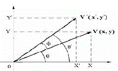
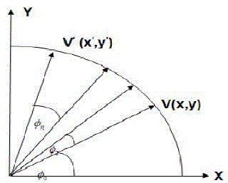
| CORDIC algorithm is derived from the general equations of vector rotation. Vector rotation can also be used for polar to rectangular and rectangular to polar conversion, for vector magnitude and as a building block in certain transforms such as the DFT and DCT [5]. The CORDIC algorithm provides an iterative method of performing vector rotation by arbitrary angle using shift and adds. The algorithm credited to Volder is derived from the general rotation transform. If a vector V with co-ordinates (x,y) is rotated through an angle Ãâ¡Ã¿ then a new vector V’ can be obtained with co-ordinates (x,y) where x’ and y’ can be obtained using x , y and Ãâ¡Ã¿ by the following method as shown in Fig.1 |
 |
 |
| V came into picture after anticlockwise rotation by an angle Ãâ¡Ã¾ . From Fig.1, it can be observed |
 |
 |
 |
 |
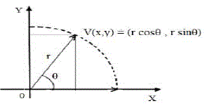
| Using Fig 2 |
 |
 |
 |
| VÃŽÃâ after anticlockwise rotation of vector V by angle Ãâ¡Ã¾ is |
 |
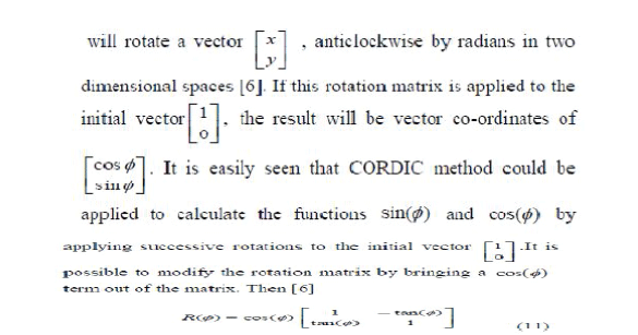
| It is well known that the rotation matrix |
 |
 |
 |
 |
 |
 |
 |
 |
 |
 |
 |
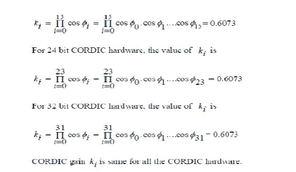 |
SCALING OPTIMIZATION AND IMPLEMENTATION
|
| We discuss here the optimization of scaling to match with the optimized set of elementary angles for the micro-rotations. |
| A. Scaling Approximation for Fixed Rotations The generalized expression for the scale-factor given by (2) can be expressed explicitly for the selected set of m1 micro rotations as |
 |
| where k(i) for 0≤i<m is the number of shifts in the ith micro-rotation. Except for k(i)=0 (i.e., rotation by 45), by binomial expansion, any term can be written as |
 |
IMPLEMENTATION OF SCALING
|
| Scaling and micro-rotations could be implemented either in the same circuit in interleaved manner or in two separate stages. The implementation of scaling as well as the micro-rotation would however depend on the level of desired accuracy, and the implementation of scaling also depends on the implementation of micro-rotations. Therefore, we discuss here the realization of the scaling circuits corresponding to different implementations of micro-rotations. |
Generalized Implementation of Scaling
|
| The shift-add circuit for scaling according to (7) is shown. The scaling circuit of Shift-add scaling circuit using hardwired pre-shifted loading can use hardwired pre-shifting for minimizing barrel-shifter complexity and could be placed after the CORDIC cell of Fig. 2 to perform micro-rotation and scaling in two separate stages. The generalized CORDIC circuit for fixed rotation to perform the micro-rotation and the scaling in interleaved manner in alternate cycles is shown. The circuit of Fig. 8 is similar to that of Fig. It involves only an additional line-changer circuit to change the path of unshifted (direct) input. The structure and function of line-changer is shown. The line-changer is placed on the unshifted input data line to keep the critical path the same as that of CORDIC cell for constant cell multiplications. |
ANALYSIS OF ERROR
|
| There are two types of error encountered during the rotation mode CORDIC iterations. Those are: approximation error and round-off error. Approximation error arises due to approximation of angle of rotation and scaling factor, while the roundoff error arises due to the finite word-length of the output components. We derive the expression for these two errors in the following subsections |
Approximation Error
|
| Proposed CORDIC operation and approximation error illustrates the CORDIC iteration which consists of a pseudo-microrotations and a scaling. In the figure, is an input vector to be rotated through angle ø. It is assumed that scaling and microrotations are implemented in two separate stages.P1 be the rotated vector after m1 micro-rotations given by |
 |
| The rotation matrix R(i) is given by (3). The i th scaling factor is given by |
 |
| such that after m2 iterations of scaling we get |
 |
| After the micro-rotations, there is a discrepancy Δø between the desired angle and the resultant angle due to the limited number of micro-rotations. Moreover, P1 cannot reach P on the circle after the scaling since KA is an approximated value which is not same as the required K. Similar to the method used, the approximation error is evaluated as a distance between the desired output V and the actual CORDIC output P2 as follows: |
 |
| For the known and fixed angle, an expectation of the approximation error can be estimated once we know the input statistics as |
 |
COMPLEXITY CONSIDERATIONS
|
| We discuss here the hardware and time complexities of the proposed design. In the existing literature we do not find similar work on CORDIC implementation of known and fixed rotations. Therefore, we compare the proposed design with the conventional CORDIC design for the rotation of unknown angle. We have used the basic CORDIC processor in [3, Fig. 2] for the implementation of conventional CORDIC. In addition, we have designed a reference architecture (see Fig. 1) for straight forward implementation of fixed rotations, and we have compared the complexities and speed performance of the proposed design with the conventional and reference design. |
RESULTS AND ANALYSIS
|
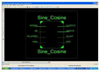 |
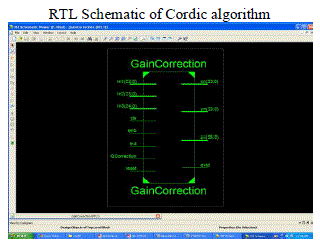 |
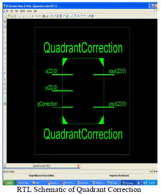 |
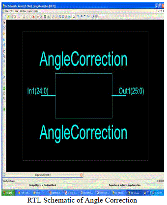 |
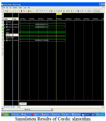 |
CONCLUSION
|
| In this paper Control CORDIC Angle correction and Quadrant correction is implemented. latency can be further reduced by Another CORDIC algorithm techniques. Overshoot problem in original CORDIC has been overcome by angle selection scheme. Due to the increasing of no. of bits complexity of hardware also increases . |
Tables at a glance
|
 |
| Table 1 |
|
Figures at a glance
|
 |
 |
 |
| Figure 1 |
Figure 2 |
Figure 3 |
|
References
|
- Volder J. E,”The CORDIC trigonometric computing technique”, IRE Trans. Electronic Computing, Volume EC-8, pp 330 - 334, 1959.
- Terence K. Rodrigues and Eari E.Swartzlander ,Jr.Fellow,”Adaptive CORDIC :Using parallel Angle Recoding to Accelerate Rotations”, IEEETransactions on Computers, Vol .59,NO.4, April 2010
- Pramod K.Meher, Senior Member ,IEEE, Javier Valls, Member, IEEE, Tso- Bing Juang , Member, IEEE, K.Sridhan, Senior Member, IEEE, andKoushik Maharatna, Member , IEEE “ 50 Years of CORDIC: Algorithms, Architectures, and Applications” , IEEE transactions on circuits and,systems,VOL.56.NO.9,September, 2009.
- Alan Sultan, “ CORDIC: How Hand calculators Calculate” Integre Technical Publishing Co.,Inc. college Mathematics journal VOL.40 NO.2 , March2009.
- Yu Hen Hu “CORDIC-Based VLSI Architectures for Digital signal processing”, IEEE Signal processing-1053-5888/92/$3.00, 1992.
- Dr. Dobbs , Michael Pascale, “Using CORDIC methods for Computations in micro-controllers” ,1 September 2000.
- Y.H .Hu, “CORDIC based VLSI architecture for digital signal processing”,IEEE signal processing Mag., pp 16-35, july 1992.
- Kia Bazargan , “CORDIC Algorithms” EE-5324-VLSI Design 2, University of Minnesto,Spring 2006.
- Tanya Vladimirova and Hans Tiggler,“FPGA implementation of sine and cosine generators Using the CORDIC Algorithm” surrey space centre,University of Surrey , Guildford , Surrey , GU2 5XH.Eric Keller,“Dynamic circuit specialization of CORDIC processor”, Nov 7, 2000.
- Quiang Gao, “Low complexity Arithmetic Implementation for DSP Radio Receiver” university of strathcyclde.(qiang.gao@eee.strath.ac.uk).
- Jean Duprat and Jean – Michel Muller “ The CORDIC Algorithm :New Results for Fast VLSI implementation” IEEE Transactions on computers ,Vol42.No.2,Feb 1993.
|