Keywords
|
| Induction motor, Space Vector Pulse Width Modulation, Fuzzy Logic Controller, Membership functions, Simulink |
INTRODUCTION
|
| Induction machines (IM) have been widely used in a variety of industrial and residential applications. Right from its inception its ease of manufacture and its robustness have made it a very strong candidate for electromechanical energy conversion device. Induction motor is existing from fractional horsepower ratings to megawatt levels. To control the induction machine there are different types of control strategies are used. The most commonly used control strategies are constant V/f control and vector control. In constant V/f control the working principle is based on the constant relation between voltage and frequency. By applying a specific phase voltage and frequency to induction machine, it can settle down at a desired speed. However, the speed control of conventional constant V/f controls lacks accuracy due to the existence of the rotor slip. This results in the increase of error between reference speed and actual speed. This method requires additional voltage and current sensors, so the complexity of the system has been increased. To overcome this problem vector control method is preferred. |
| The vector control algorithm is based on two currents. An induction motor can be modeled most simply using two quadrature currents rather than the familiar three phase currents actually applied to the motor. These two currents called direct (Id) and quadrature (Iq) are responsible for producing flux and torque respectively in the motor. In addition, at least two current sensors and one position sensor is necessary to meet the minimum feedback requirements of vector control. As a result, the failure of the sensor or even the drift of system parameters could potentially result in system malfunction. |
| This paper has simple, cost-effective and reliable control strategy as a backup control strategy to continue operate the system in case of failure of current and voltage feedback sensors. In this method the space vector modulation technique has been used because it generates less harmonic distortion in the output voltages and or currents applied to the phases of an AC motor and to provide more efficient use of supply voltage compared with sinusoidal modulation technique. The fuzzy logic bases intelligent controller is used instead of the PI controller, excellent control performance can be achieved even in the presence of parameter variation and drive non-linearity. |
BLOCK DIAGRAM OF DIGITAL PWM SPEED CONTROL USING FUZZY LOGIC CONTROLLER
|
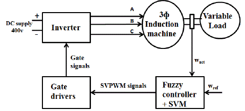
| The proposed block diagram consists of inverter, fuzzy logic controller. The inverters will coverts the D.C supply into A.C supply. Depending on the speed error fuzzy controller produces the output as duty cycle .If modulation index varies the duty cycle inverter will be changed. Among various modulation techniques for a inverter, SVPWM technique is an attractive technique due to the following advantages. It directly uses the control variable given by the control system and identifies each switching vector as a point in complex space. The proposed block diagram of speed control is shown in the Fig 1. |
| A. Principle of Space Vector Modulation |
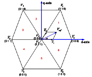
| The concept of space vectors is derived from modulating the inverter output voltage from the rotating field of AC. In this technique the three phase quantities can be transformed to their equivalent 2-phase quantity either in synchronously rotating frame or stationary frame. From this 2-phase component the reference vector magnitude can be found and used for modulating the inverter output. By using active and zero space vectors the active and zero switching states can be determined. The space vector diagram for the three-level inverter is shown in the Fig 2. where the six active vectors V1 to V6 form a regular hexagon with six equal sectors (I to VI). The zero vector V0 lies on the center of the hexagon. |
| In order to obtain the output of inverter supported by SVPWM as sinusoidal the reference vector locus with respect to time should be a circle instead of hexagon as locus of the vector sum of three voltages gives a circle. To achieve the above capsule, the vector in each sector is sampled for a specific duration using active and zero vectors and hence we can obtain required vector of corresponding instant. The sampling duration for active and zero vectors to produce the vector at corresponding instant can be obtained using volt second balance equation. |
| B. Realization of Space Vector PWM |
| Step 1: Determine Vd, Vq, Vref and angle (α) |
| Step 2: To determine the time duration T1, T2, T0 in each sector |
| Step 3: To determine the switching time of each transistor (S1 to S6) |
| C. Determine Vd, Vq, Vref And Angle (α) |
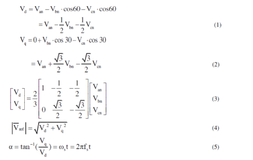
| For a given Magnitude (length) and position, Vref can be synthesized by three nearby stationary vectors, based on which the switching states of the inverter can be selected and gate signals for the active switches can be generated.The Coordinate transformation abc to dq will be, |
 |
| D. To Determine the Time Duration T1, T2, T0 in Each Sector |
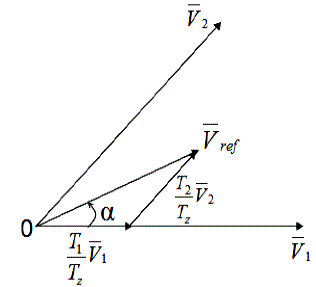
| The reference vector as a combination of adjacent vectors at sector 1 is shown in Fig 3.The switching time duration at Sector 1, |
 |
 |
 |
 |
 |
| E. To Determine the Switching Time of Each Transistor (S1 To S6) |
| The objective of space vector PWM technique is to approximate the reference voltage vector Vref using the eight switching patterns. Based on this the switching time at each sector is summarized in the table I. According to the sector in which the reference signal is located based on that switching time between the two vectors can be determined. |
| F. Implementation of Fuzzy Logic Controller |
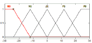
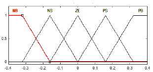
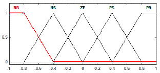
| The Fuzzy Logic Controller initially converts the crisp speed error and change in speed error variables into fuzzy variables and then are mapped into linguistic labels. Membership functions are corresponding with each label as shown in which consists of two inputs and one output. The linguistic labels are classified into five groups. They are, |
| • NB-Negative Big • NS- Negative Small • Z-Zero • PS-Positive Small • PB-Positive Big • PB-Positive Big |
| In Defuzzification, the fuzzy output set is converted to a crisp number. Some commonly used techniques are the centroid and maximum methods. In the centroid method, the crisp value of the output variable is computed by finding the variable value of the centre of gravity of the membership function for the fuzzy value. In the maximum method, one of the variable values at which the fuzzy set has its maximum truth value is chosen as the crisp value for the output variable. |
| They are wo different types in the Fuzzy Interference System. They are, |
| 1. Mamdani FIS 2. Sugeno FIS |
| The antecedent describes to what degree the rule applies, while the conclusion allocate a fuzzy function to each of one or more output variables. Most tools for working based on the fuzzy expert systems allow more than one conclusion per rule. The knowledge base is defined as the set of rules in a fuzzy expert system. The difference between the two methods lies in the consequent of fuzzy rules. Fuzzy sets are used as rule consequents in Mamdani FIS and linear functions of input variables are used as rule consequents in Sugeno’s method. Each of the inputs and the output contain membership functions with all these five linguistics. The Fig 4 shows the speed error, Fig 5 shows the change in speed error and Fig 6 shows the duty cycle. |
| The inputs are speed error and change in speed error and the output is duty cycle .The mapping of the fuzzy inputs into the required output is derived with the help of a rule base as given in Table II. |
SIMULATION RESULTS
|
| In order to verify the practicability of the proposed Digital PWM speed control, simulation has been implemented using Matlab/Simulink. A 50 Hz,4 pole induction machine is used with a rated speed of 1440rpm.The simulink models were run according to the following data. Pw = 7.5 kw, Vs=400 V, Trated =49.13Nm, Rs=0.7384Ω, Ls=0.003045H. |
| A. Output Speed Response Of Induction Motor Using FLC And SVPWM |
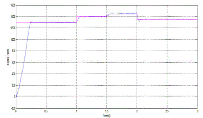
| The output speed response of IM drive using Fuzzy logic control and SVPWM technique is shown in the Fig 9. In this paper four speed has been controlled for different application. The reference speed will be 1300 rpm from 0 to 1 sec, 1400 rpm from 1 to 1.5 sec, 1450 rpm from 1.5 to 2 sec and above 2sec the speed will be 1350 rpm. In this paper the overshoot is less also the actual speed can be settled as fast as possible by using the fuzzy logic controller. |
CONCLUSION
|
| In this proposed method, Fuzzy logic controller based speed control of Induction Motor drive have been simulated using MATLAB. The simulated results of FLC have shown improved performance over the PI controller. It has been seen that SVPWM technique generate lesser Harmonic distortion in the output voltage and current applied to the phases of an induction motor. Owing to its simplicity this strategy can be used as backup control strategy in the event of sensor failure. |
Tables at a glance
|
 |
 |
| Table 1 |
Table 2 |
|
Figures at a glance
|
 |
 |
 |
 |
 |
| Figure 1 |
Figure 2 |
Figure 3 |
Figure 4 |
Figure 5 |
 |
 |
 |
 |
| Figure 6 |
Figure 7 |
Figure 8 |
Figure 9 |
|
References
|
- F.D.S.Cardoso, J.F.Martins, V.F.Pires, “A Comparative Study of a PI,Neural Network and Fuzzy Genetic Approach Controllers for an ACDrive” 5th International Workshop on Advanced Motion Control,vol.35,no.2. pp.375 –380, Feb 1998.
- Do-Hyun Jang, “Problems Incurred in a Vector-Controlled Single-Phase Induction Motor, and a Proposal for a Vector –Controlled Two-PhaseInduction Motor as a Replacement”, IEEE Trans. Power Electronics ,vol.28,no.1.pp.526-536, Jan.2013.
- S.EbanezarPravin,R.NarcissStarbell, “Induction Motor Drive Using Seven Level Multilevel Inverter for Energy Saving in Variable TorqueLoad Application”, IEEE conf.Computer, Communication and Electrical tech-ICCCET ,vol.74.no.3.pp.462-468, March 2011.
- A.Khaligh, A. M. Rahimi, Y. J. Lee, J. Cao, A. Emadi S. D. Andrews,C. Robinson, and C. Finnerty, “Digital control of an isolated active hybridfuel cell/Li-ion battery power supply”, IEEE Trans. Vehicular Tech., vol. 56,no.1. pp. 3709 – 3721, Nov 2007.
- A.Khaligh and A. Emadi , “Pulse Adjustment, a Novel Digital Control Technique, for Control of a DC-DC Buck-Boost Converter Operating inDiscontinuous Conduction Mode and Driving Constant Power Loads”, IEEE conf. Vehicle Power and propulsion,vol.52,no.3. pp.1-5,2006.
- M.LakshmiSwarupa, G.Tulasi Ram Das and P.V. Raj Gopal, “Simulation and Analysis of SVPWM Based 2-Level and 3-Level Inverters forDirect Torque of Induction Motor’, International Journal of Electronic Engineering Research ISSN 0975 – 6450.vol- 1 no.3, pp. 169–184, Feb 2009.
- Y. Lai , “Machine Modeling and Universal Controller for Vector-Controlled Induction Motor Drives”, IEEE Trans. Energy Conversion, vol-18,no.1, pp.23-32, Mar 2003.
- Munoz-Garcia , T. A. Lipo and D. W. Novotny , “A New Induction Motor V/f Control Method Capable of High-Performance Regulation at LowSpeeds”, IEEE Trans. Ind. App., vol. 34, no. 4, pp.813-821, Jul/Aug 1998.
- J.A.Santisteban and R. M. Stehan , “Vector Control Methods for Induction Machines: An Overview”, IEEE Trans. Education, Vol. 44,No. 2, pp.170-175, May 2001.
- A.Sathyan, N. Milivojevic, Y. Lee, M. Krishnamurthy and A. Emadi , “An FPGA-Based Novel Digital PWM Control Scheme for BLDC MotorDrives”, IEEE Trans. Ind. Electron., Vol. 56, No.8, pp.3040-3048, Aug 2009.
- M. Tsuji, S. Chen, S. Hamasaki , X. Zhao and E. Yamada , “A Novel V/f Control of Induction Motors for Wide and Precise Speed Operation” ,IEEE Conf. Power Electronics, Electrical Drives, Automation and Motion.Vol.53,pp.1130-1135,2008.
- XiaodongShi,Mahesh Krishnamurthy , “Concept and Implementation of a Simplified Speed Control Strategy for Survivable Induction MotorDrives”, IEEE conf.Computer, Communication and Electrical tech-ICCCET ,Vol.74.No.3.pp.556-561, Jul 2011.
|