Keywords
|
| Fast Fourier Transform (FFT), Floating-Point, Radix-2 Butterfly, VHDL |
INTRODUCTION
|
| In computation, floating point format represents another way to describe the real number which can support wide range of values. It can be represented in the form as |
| Significant digits x base exponent |
| Since the real numbers cannot be implemented directly in the hardware, so floating point number representation is used. Commercial floating point algorithm consumes more power and requires more memory. The two new architectures for addition, subtraction and product for floating point number namely Fused DP and Fused AS unit. This new architecture reduces computation complexity, data storage, area, and power consumption. Section 2 describes IEEE-754 Standard. Section 3 describes Fast Fourier Transform. The next two sections describe the Fused DP and Fused AS units. Subsequent sections describe the use of these two operations to implement FFT butterfly units. |
IEEE-754 STANDARD
|
| `The IEEE Standard for Floating Point Arithmetic (IEEE 754) is a technical standard for floating point computation established in 1985 by the Institute of Electrical and Electronics Engineers (IEEE). Many hardware floating point units use the IEEE 754 standard. The current version, IEEE 754-2008 published in August 2008, includes nearly all of the original IEEE 754 1985 standard and the IEEE Standard for Radix-Independent Floating-Point Arithmetic (IEEE 854- 1987). |
| The advantage of floating-point representation over fixed point and integer representation is that it can support a much wider range of values. For example, a fixed point representation that has seven decimal digits with two decimal places can represent the numbers 12345.678, 123.45, 1.23456 and soon, whereas a floating-point representation (such as the IEEE 754 decimal 32 format) with seven decimal digits could in addition represent 1.234567, 0.00001234567, 1234567000, and so on. The floating-point format needs slightly more storage (to encode the position of the radix point), so when stored in the same space, floating-point numbers achieve their greater range at the expense of precision |
| IEEE floating point numbers have three basic components: the sign, the exponent, and the mantissa. The mantissa is composed of the fraction and an implicit leading digit. The exponent base (2) is implicit and need not be stored. The following Table 1 shows the layout for single (32-bit) and doubles (64-bit) precision floating-point values. The number of bits for each field are shown (bit ranges are in square brackets). |
| A) Sign Bit |
| The sign bit is as simple as it gets. 0 denotes a positive number, 1 denotes a negative number. Flipping the value of this bit flips the sign of the number. |
| B) Exponent |
| The exponent field needs to represent both positive and negative exponents. To do this, a bias is added to the actual exponent in order to get the stored exponent. For IEEE single precision floats, this value is 127. Thus an exponent of zero means that 127 is stored in the exponent field. For double precision, the exponent field is 11 bits, and has a bias of 1023. |
| C) Mantissa |
| The mantissa, also known as the significant, represents the precision bits of the number. It is composed of an implicit leading bit and the fraction bits. |
FAST FOURIER TRANSFORM
|
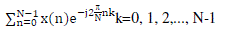
| The number of complex multiplication and addition operations required by the simple forms both the Discrete Fourier Transform (DFT) and Inverse Discrete Fourier Transform (IDFT) is of order N 2 as there are N data points to calculate, each of which requires N complex arithmetic operations. |
| For length n input vector x, the DFT is a length n vector X, with n elements: |
 (1) (1) |
| As the name suggests, FFTs are algorithms for quick calculation of Discrete Fourier Transform of a data vector. The FFT is a DFT algorithm which reduces the number of computations needed for N points from O (N2) to O (N log N) where log is the base-2 logarithm. |
| The Radix 2 algorithms are useful if N is a regular power of 2 (N=2p). There are two different Radix 2 algorithms, the so called Decimation in Time (DIT) and Decimation in Frequency (DIF) algorithms. Decimation in Time (DIT) computational elements consist of complex multiplications followed by a sum and difference network. Decimation in Frequency (DIF) computational elements consist of a sum and difference network followed by complex multiplications. |
FUSED DOT PRODUCT UNIT
|
| In many DSP algorithms the sum of the products of two sets of operands (dot-product) is a regularly used operation. It has some advantages over discrete floating-point multipliers in a floating point unit design. In usual floating-point dot product is carried out with two multiplications and an addition. The multiplications are performed in parallel with two floating-point multipliers followed by a floating-point adder which is costly in teams of silicon area and in power consumption. But in fused floating point unit, the two floating point multipliers, adder and subtraction are performed in same unit which reduces the silicon area and power consumption. The implementation of a floating point fused dot-product unit shown in Fig.1. |
| The floating-point two-term fused dot product (Fused DP) unit computes a two term dot product: |
 (2) (2) |
| The usual dot product adds the two products as shown in (2), but the Fused DP unit performing both addition and difference of the two products, so that the power and area is reduced when compared to a usual parallel discrete dot product implementation, since the rounding and normalization logic of both of the multipliers are eliminated. Multiplies two sets of operands and add/subtract the products. The two products need not to be normalized. Only the final result is normalized and rounded which reduces delay and silicon area. |
FUSED ADD-SUBTRACT UNIT
|
| The usual parallel Add-Subtract unit which has separate add and subtract unit in parallel. This may increase the silicon area and consumes more power. Alternatively, in fused floating point Add-Subtract unit is used which reduce the silicon area and power consumption. It combines both addition and subtraction operations as a single unit to perform complex addition and subtraction operation. Sharing the exponent comparison and arrangement reduces complexity. The implementation of a floating point fused Add-Subtract unit shown in Fig.2. |
| The floating-point fused add-subtract unit (Fused AS) performs an addition and a subtraction in parallel on the same pair of data as shown as: |
 (3) (3) |
| The both floating point fused dot product unit and fused add-subtract unit are designed based on behavioural modelling using VHDL. |
RADIX-2 FFT
|
| To express the benefit of the Fused DP and Fused AS units for FFT implementation, FFT butterfly unit designs using both the discrete and the fused units have been made. First radix-2 decimation in time FFT butterfly is designed. It is shown in Fig. 3. All lines carry complex pairs of 32-bit IEEE-754 numbers or 64-bit IEEE-754 numbers and all operations are complex. A discrete implementation of complex adder uses two real adders. A discrete implementation of complex subtraction uses two real subtract and for discrete implementation of complex multiplication uses four real multipliers and two real adders. The complete butterfly consists of six real adders and four real multipliers. The complex add and subtract can be performed with two fused add subtract units and the complex multiplication can be performed with two fused dot product units. |
| In comparing the discrete and fused radix-2 butterfly units, the fused architecture requires less area and is faster than the discrete implementation. Radix-2 FFT butterfly is performed for both single (32-bit) and double (64-bit) precisions and compared. |
SIMULATION RESULT
|
A) 2-Point Fused FFT (Single Precision)
|
| X0= (01000001000010110011001100110011, 0100000010110000000000000000000) |
| X1= (01000000010000000000000000000000, 01000000111111000111101011100001) |
| Y0= (00000000000000000000000000000000, 10000000100000000000000000000000) |
| Y1= (00000000000000000000000000000000, 10000000100000000000000000000000) |
B) 2-Point Fused FFT (Double Precision)
|
| X0= (0011111110000000000000000000000000000000000000000000000000000000, |
| 00000000000000000000000000000000000000000000000000000000000000) |
| X1= (101111111000000000000000000000000000000000000000000000000000000, |
| 00000000000000000000000000000000000000000000000000000000000000) |
| Y0= (000000000000000000000000000000000000000000000000000000000000000, |
| 100000000000000000000000000000000000000000000000000000000000000) |
| Y1= (010000000000000000000000000000000000000000000000000000000000000, |
| 100000000000000000000000000000000000000000000000000000000000000) |
C) FPGA Implementation
|
| 1) Spartan-6 FPGA |
| Unified Learning Kit is based on Texas Instruments OMAP3530 application processor & Spartan-6 FPGA. The Spartan-6 family provides leading system integration capabilities with the lowest total cost for high-volume applications. The thirteen-member family delivers expanded densities ranging from 3,840 to 147,443 logic cells, with half the power consumption of previous Spartan families, and faster, more comprehensive connectivity. Spartan-6 FPGAs are the programmable silicon foundation for Targeted Design Platforms that deliver integrated software and hardware components that enable designers to focus on innovation as soon as their development cycle begins. |
| Supporting Appliances : The Spartan-6 FPGA supports interfaces such as Ethernet, FPGA HDR2 20-pin Header, Keypad connector(4X4), FPGA Expansion connector, Mictor connector, ADC, DAC, LED, UART Transceiver, 7 segment LED, 16x2 Char LCD, Oscillators (10 & 100Mhz), DDR2 SDRAM, PROM, Dip Switches. |
| 2) 70-Pin Expansion connector |
| Most of FPGA signals are directly driven by FPGA which are 3.3V voltage level. For some signals, level translators are used to convert the 1.8V FPGA signals to 3.3V compatible signals. |
| Using 70-Pin Expansion connector leds are interfaced with FPGA to display the outputs of 32 bit FFT Processor is shown in figure 7. |
| D) Comparison |
| 1) 32-bit FFT |
| 2) 64-bit FFT |
CONCLUSION
|
| This paper explains about the design of two new fused floating-point arithmetic units and their application to the implementation of FFT butterfly operations. Using this architectures area, delay and power is reduced for radix-2 FFT butterfly and compared. From the results it is proved that fused arithmetic implementation is better than parallel arithmetic implementation. By double precision it is shown that the result is more accurate than single precision implementation. Fig. 8 and 9 shows the comparison between single precision and double precision for various parameters. In future pipelined architecture of fused arithmetic can design. |
Tables at a glance
|
 |
| Table 1 |
|
Figures at a glance
|
 |
 |
 |
 |
 |
| Figure 1 |
Figure 2 |
Figure 3 |
Figure 4 |
Figure 5 |
 |
 |
 |
 |
| Figure 6 |
Figure 7 |
Figure 8 |
Figure 9 |
|
References
|
- Earl E. Swartzlander Jr., and Hani H.M. Saleh, “FFT Implementation with Fused Floating-Point Operations,” in IEEE Transactions[on Computers, 2012.
- IEEE Standard for Floating-Point Arithmetic, ANSI/IEEE Standard 754-2008, Aug. 2008
- SnehaN.kherde and MeghanaHasamnis, “Efficient Design and Implementation of FFT,” in International Journal of Engineering Science[and Technology, 2011.
- H.H. Saleh and E.E. Swartzlander, Jr., “A Floating-Point Fused Dot-Product Unit,” Proc. IEEE Int’l Conf. Computer Design (ICCD), 2008.[[5
- H.H. Saleh, “Fused Floating-Point Arithmetic for DSP,” PhD dissertation, Univ. of Texas, 2008.[[6
- H. Saleh and E.E. Swartzlander, Jr., “A Floating-Point Fused Add-Subtract Unit,” Proc. IEEE Midwest Symp. Circuits and Systems[(MWSCAS), pp. 519- 522, 2008.
|