Keywords
|
| MOSFET, IGBT, Cascaded Multilevel Inverter, H-Bridge Multilevel Inverter, Battery, Diode. |
INTRODUCTION
|
| Three basic multilevel inverter topologies are the Neutral Point Clamped (NPC) or diode clamped, the flying capacitor (FC) or capacitor clamped and the cascaded H-bridge [1].The drawbacks of NPC topology are unequal voltage sharing among series connected capacitor that result dc-link capacitors are unbalanced and requiring a great number of clamping diodes for higher level. The FC as clamping devices has several attractive properties when compared with NPC [1]-[5]. The advantage of this transformer less operation. It can be classified into two types namely single source and multi-source multilevel inverter. Single source system has only one DC source [8]. In single source system the remaining are clamping diodes or capacitors. It is classified into two types namely diode clamped multilevel inverter and flying capacitor multilevel inverter [1]-[9].The main disadvantage of flying capacitor inverter is that it requires large number of capacitors. Diode clamped inverter restricts the use of high power range of operations [4]-[6]. The shortcomings in single source systems are overcome by introducing a multisource multilevel inverter. |
| In multi-source inverter system has two or more DC sources and it is a series power cells. It classified into two types namely cascaded H-Bridge multilevel inverter and Hybrid H-Bridge multilevel inverter. H-Bridge multilevel inverter can be easily scaled to the power levels [7]. However, it requires large number of semiconductor switches [1]- [7].Multilevel inverter has gained more attention for high power application in recent years which can operate at high switching frequencies while producing low order harmonic components [1].This inverter not only achieves the high power ratings but also enables the use of renewable energy sources such as photovoltaic, wind and fuel cells that can be easily interfaced to a multilevel inverter. For a medium voltage grid, it is connected to one power semiconductor switch directly [1]-[2].In multilevel inverter, the power quality is improved as the number of levels increases at the output voltage [3]. The number of switching devices and other components increases along with the cost and complexity of the control circuit and thereby reducing the overall reliability and efficiency of the inverter. |
SYSTEM MODEL
|
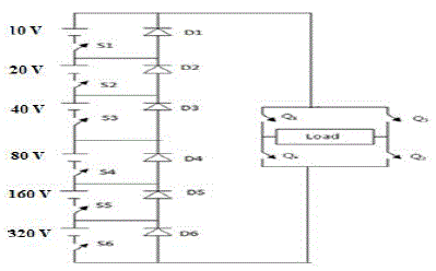
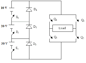
| A new basic multilevel module (MLM) for the multilevel converter has been proposed. The proposed topology is a combination of MLMs and full-bridges converter. The proposed topology extends the design flexibility and the possibilities to optimize the converter for various objectives. It has been shown that the structure, consisting of MLMs with two switches has the minimum number of switches for a given number of voltage level. The proposed multilevel inverter has a general structure of the hybrid multilevel inverter as shown in Fig 1. Each stage has separate voltage source (Vdc1, Vdc2, and Vdc3) connected in cascade.Only One H Bridge is required for the single phase system along with a switch and a diode for each voltage source. In the conventional method, twenty one(21) switches are used to obtain hundred and twenty five (125)levels. Due to twenty one switches, the harmonics, switching losses, cost and the total harmonic distortion are increased. This proposed topology increases the level to 127 with only 10 switches and six diodes. Renewable energy sources such as photovoltaic, wind, and fuel cells can be easily interfaced to multilevel inverter system for a high power application. |
PRINCIPLE OF OPERATION
|
| The basic operation of the proposed system is to turn on s1 and turn off s2 and s3.The Output voltage is +1v.When the Switch s2 is on and turn off s1 and s3.The output voltage is +2v.The switch s3 is on switch s1 and s2 are turn off. Similarly all the combinations of switching states are turn on and off with respect to the driver circuit. Only one Hbridge is required for get the both positive and negative output voltage levels of the system. The advantage of modified system increases the level with low number of switches. |
| The S number of DC sources or stages are calculated by using the equation, |
 |
| The voltage on each stage can be calculated by using the equation, |
 |
| The number of switches used in the topology is given by the equation, |
 |
SIMULATION SETUP
|
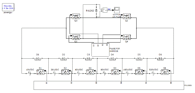
| The optimal multilevel structure with minimum used gate driver circuits based on the topology proposed is simulated usingMatlab.The proposed system with 10 switches and 6 diodes is simulated for 127 levels for 1V. The output of pulse repeater is given to the switching devices (IGBT). The switching pulse amplitude is 1V. The control voltages for switching devices S1, S2 and S3 and for inverter switches Q1, Q2, Q3 and Q4 is through gate triggering circuits shown in Fig 2. For validating the results, the existing system with 21 switchesi.e .Three legs each with 7 switches is also simulated. The reason for increased number of switches in the existing system is that each leg has separate H-bridge. To overwhelm this drawback, the proposed system uses only one H-Bridge for any levels. The efficiency of the proposed system is high when compared to existing method since the output waveform is sinusoidal with reduced lower order harmonics. |
HARDWARE DESIGN
|
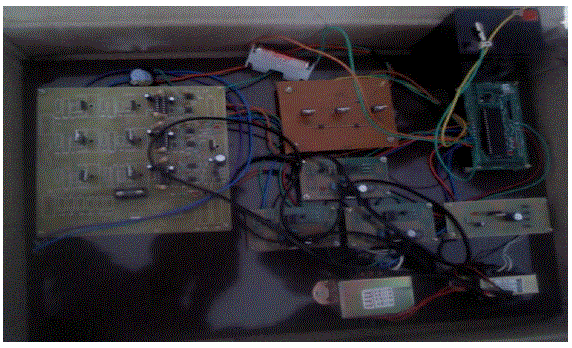
| The inverter is realized in hardware with seven switches and three diodes. The PIC microcontroller is used for generating control pulses.The hardware is have PIC 16F877A microcontroller. The DC supply given to sub inverters and the gating pulses are generated using microcontroller to the driver circuit and from the driver circuit the pulses are driven into the sub inverter circuit. |
| The hardware circuit consists of the following. |
| 1. power supply |
| 2. driver circuit |
| 3. micro controller |
| A steady state dc voltage is obtained by rectifying the ac voltage, then filtering to a dc level, and finally, regulating to obtain a desired fixed dc voltage. The regulation is usually obtained from an IC voltage regulator unit, which takes a dc voltage and provides a somewhat lower dc voltage, which remains the same even if the input dc voltage varies, or the output load connected to the dc voltage changes. A power supply can be built using a transformer connected to the ac supply line to step the ac voltage to a desired amplitude, then rectifying that ac voltage, filtering with a capacitor and RC filter, if desired, and finally regulating the dc voltage using an IC regulator. Microcontroller is a general purpose device, which integrates a number of the components of a microprocessor system on to single chip. It has inbuilt CPU, memory and peripherals to make it as a mini computer. A microcontroller contains the following. |
| 1. The CPU core |
| 2. Memory(both ROM and RAM) |
| 3. Some parallel digital i/o Microcontrollers will combine other devices such as: |
| 4. A timer module to allow the microcontroller to perform tasks for certain time periods. |
| 5. A serial i/o port to allow data to flow between the controller and other devices such as a PIC or another microcontroller. |
| 6. An ADC to allow the microcontroller to accept analogue input data for processing. |
RESULS AND DISCUSSION
|
| The structure of optimal multilevel with minimum used switches with minimum driver circuits is simulated using Matlab. The same scenario is realized through hardware. For comparing the results, the existing system with 21 switches is also simulated. The lower order harmonics of the proposed system is significantly reduced. Hence it is inferred that the proposed system results are better when compared to existing system with reduced number of switches. The same results are observed when the setup is implemented in hardware. The efficiency of multilevel inverter predominates the existing with reduced Total Harmonic Distortion and switching losses. |
CONCLUSION
|
| Powerquality is improved with the increase in number of levels of multilevel inverter. The number of switching devices and other components ultimately increase the cost and control complexity. Hence, a multilevel inverter of 127 levels with only ten switches and six diodes is proposed. The system uses a bypass diode technique with only one H-bridge for any levels. Simulation is carried out in Matlaband the experiment is carried out in hardware. The results are promising since the total harmonics distortion of proposed method is dramatically reduced with reduced switches, switching losses, cost, and low order harmonics with improved efficiency. |
Tables at a glance
|
 |
| Table 1 |
|
Figures at a glance
|
 |
 |
 |
 |
 |
| Figure 1 |
Figure 2 |
Figure 3 |
Figure 4 |
Figure 5 |
|
References
|
- JavadEbrahimi, ,EbrahimBabaei, and Gevorg B. Gharehpetian, “A New Multilevel Converter Topology With Reduced Number Of Power Electronic Components”IEEE TRANSACTIONS ON INDUSTRIAL ELECTRONICS, VOL. 59, NO. 2, FEBRUARY 2012 655
- H.Abu-Rub, J.Holtz, J.Rodriguez, andG.Baoming, “Medium voltage multilevel converters-State of the art, challenges and requirements in industrial applications,”IEEETrans.Ind.Electron, vol.57, no.8, pp.2581-2596, Aug.2010.
- Ali Khajehoddin, S., AlirezaBakhshai , Praveen K. Jain, “A Simple Voltage Balancing Scheme for M-Level Diode Clamped Multilevel Converters Based on A Generalized Current Flow Model,” IEEE Trans. Power Elect., Vol. 23, No. 5., 2008)
- AnshumanShukla, ArindamGhoshandAvinash Joshi, “Improved Multilevel Hysteresis Current Regulation and Capacitor Voltage Balancing Schemes for Flying Capacitor Multilevel Inverter,” IEEE Trans. on Power Elect., Vol. 23, No. 2, 2008.
- E.Babaei and S.H.Hosseini, “New cascaded multilevel inverter topology with minimum number switches,”J.Energy converters. Manag., vol. 50, no.11, pp. 2761-2767, Nov. 2009.
- K. Corzine,., S. Sudhoff, and C. Whitcomb, “Performance Characteristics of a Cascaded Two Level Converter,” IEEE Trans. on Energy Conversion, Vol. 14, No. 3, pp. 433 –439, 1999.
- K. Corzine, and Y. Familiant, “A New Cascaded Multilevel H-Bridge Drive,” IEEE Tran. Power Elect, Vol. 17, No. 1, pp. 125–131, and 2002.
- Z.Du, L.m.Tolbert, J.N.Chiasson, and B.Opineci, “A cascaded multilevel inverter using a single dc power source,” in Proc. IEEE APEC, 2006, pp.426-430
- EbrahimBabaei , “A Cascade Multilevel Converter Topology with Reduced Number of Switches,”IEEE Trans. Power Elect., Vol. 23, No. 6, 2008.
- Sung Geun Song, Cascaded MultilevelInverter Employing Three Phase Transformers and Single DC Input, IEEE Trans. on Ind. Elect. Vol. 56, No. 6, June, 2009.
- Y. S. Lai, and F. S. Shyu, Topology for Hybrid Multilevel Inverter, IEE Proc. Elect. Power Appl., Vol. 149, No. 6, 2002.
|