Keywords
|
| Hybrid Active Power Filter for 1ph&3-ph system, Boost circuit, Sinusoidal PWM |
INTRODUCTION
|
| The application of power electronic in power conversion shows drawbacks that lead to power quality problems which could relate to harmonics affecting communication interference, heating, solid-state devices malfunction, resonance . Solutions involve several techniques that include the use of passive and active power filter (APF). A more advance approach is the use of hybrid filters amongst other involves the use of both the passive filter and shunt APF in combination. They are being used to eliminate both the lower order and higher order harmonics. The passive filter is normally designed to eliminate the bulk of load-current harmonic leaving the more complex problems to be solved by the APF. |
| Shunt APF normally operates using pulse width modulation (PWM) inverter techniques to inject the required non-sinusoidal current requirements of nonlinear loads but is complex with the number of switches in use . Another approach is the use of series active power filter that uses basic bridge-diode circuit, boost circuit and an inductor . Single phase converter produces a relatively high proportion of ac ripple voltage at its dc terminal, it is undesirable becau se of its heat producing effect. A smoothing needed to get continuous operation. It can be minimized by increasing number of pulses. Three phase ac supply with a suitable transformer connection permits an increasing the pulse number. When the number of pulses increased out put voltage gets smoothen. So here we are implementing an extension of single phase hybrid active power filter with three phases HAPF. |
| The time-domain approach is used to control the power switch of proposed PAPF during compensation process. This approach is based on the principle of holding the instantaneous current within some reasonable tolerance of a sine wave . The error is computed from the difference of instantaneous actual current signal with its reference signal, normally pure sine wave. This error is then conditioned and processed to obtain the required switching pattern known as the pulse wave modulation (PWM) wave. A simple proportional integral control method is implemented to aid response from the control which uses a supply current detection to accomplish shunt APF tasks. A simple LC filter is used in conjunction to study its effects. |
PROPOSED HYBRID ACTIVE POWER FILTER
|
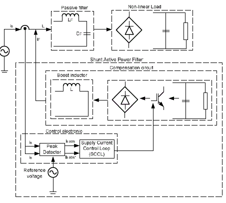
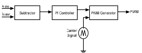
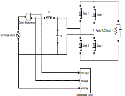
| The new proposed hybrid APF consists of two types of filter; simple LC passive filter and a PAPF for removing both high order and low order harmonic components. Fig. 1 shows the arrangement of proposed hybrid APF and in block diagram of Fig. 2 with its control components of Fig.3 |
| The PAPF is used to inject equal but opposite current into the system to mitigate the distortion current to a sinusoidal form; in phase and time with the voltage supply. The new proposed PAPF topology only consist a single active power switch (IGBT) in order to simplify the compensation circuit and reduce the switching stress. |
| The SCCL (fig.1) is used to monitor the supply current waveform and make corrections by current compensation techniques. If the supply current is distorted, the SCCL will respond by providing switching signal to the IGBT that will inject the current compensation from the PAPF circuit to the mains to compensate the distorted supply current into a sinusoidal form. Unipolar switching is proposed due to the use of one power switch in the system. The c o m p e n s a t i o n circuit uses a boost and PWM technique to generate the injected current into the system. |
| In this work, active PWM as active current wave shaping is used for switching control. This technique allows active comparison of the error signal with the carrier signal to ensure error is kept within the boundaries of the carrier peaks at all times. The active PWM operates by comparing the corrected signal with the carrier signal to produce the required PWM control. When sinusoidal signal has magnitude larger than or equal to the carrier signal, the comparator output (PWM sequence) is higher. A proportional integral (PI) control algorithm is used to regulate the error. |
OPERATION OF SHUNT APF
|
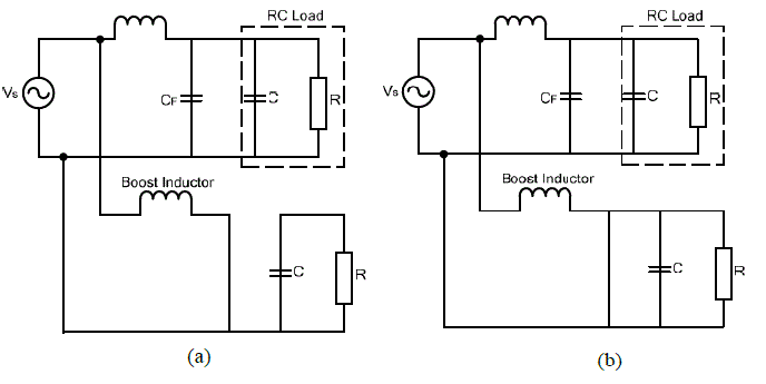
| The operation of the PAPF is best described by the illustration as shown in Figure 4 to inject the required current into the system. When switch is turned ON (Figure 4(a)), diode D5 is reversed biased. Thus the output stage is isolated from the system. The input supplies energy to the boost inductor that causes inductor current to increase linearly with ramp behaviour. The energy stored in the inductor can be used for compensation purposes. When the switch is turned OFF, diode D5 is forward biased as shown in the equivalent circuit of Fig. 4(b). There exists a change in current. Since the inductor cannot change instantaneously, the voltage in the inductor reverses its polarity to maintain constant current. In this stage, the current will flow through the inductor, diode D5 and the compensating load. |
| Three-Phase Converters : |
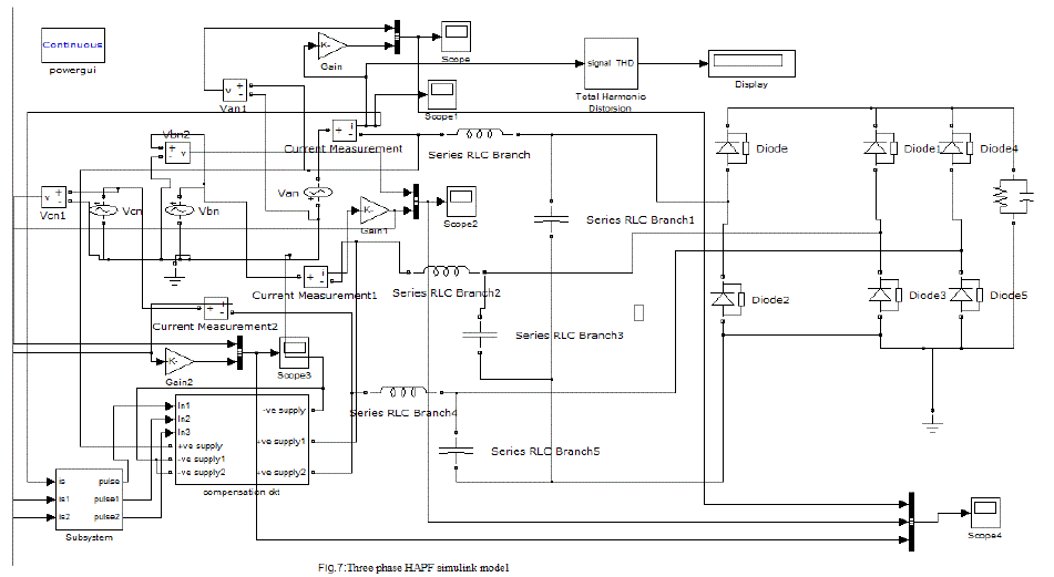
| In three phase rectifiers in this project that combines the operation of normal rectifier operation and respective characteristics . |
| The operation of 3-ph rectifiers can be done with two types of circuit arrangements namely half wave and full wave rectifiers. In half rectifiers there are 3 switches (Diodes or thyristors) are used, for controlling purpose we are using the scr’s as switches to control the load side parameters. In this 3 phase transformer used at input side as source voltage , here each switch can operate for 120 degrees apart as three phases combinely getting as total of 360 degree operation. Each leg in 3 phase rectifiers are arranged so that it gives complete operation to satisfy the desired load condition at output side . |
| As a part of introduction in this implementing of HAPF it will removes the Harmonics which will creates in 3phase systems when feeding with Non-linear loads . |
| By implementing 3-ph HAPF we can remove harmonics and THD will also decreases as like 1-ph systems |
The ripple at the output voltage is given by 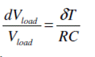 |
| where R is the load resistance and C is the capacitance. |
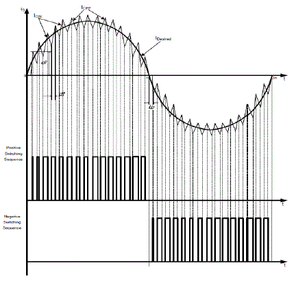
| Fig. 5 shows the waveform of the desired supply with the compensation current from boost technique. During switching on, the inductor is linearly ramping while when switching is off, energy from inductor and from supply will transfer to the load. Therefore the current from inductor will decrease linearly. |
SIMULATION MODEL
|
| In this work, MATLAB/Simulink was used to analyze the behaviour of the proposed system. Fig. 6 shows the proposed system that consists of a simple LC filter with PAPF shunt-connected with the non-linear load and main supply.. A gate drive circuit was used to boost the small PWM signal into an appropriate level for turning ON of the IGBT and to provide physical isolation between the power and electronics section. |
SIMULATION RESULT S
|
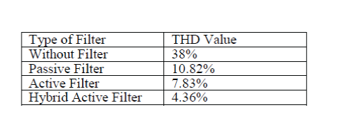
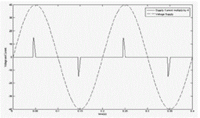
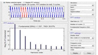
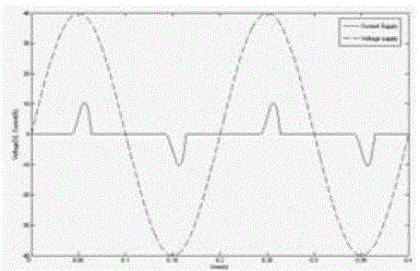
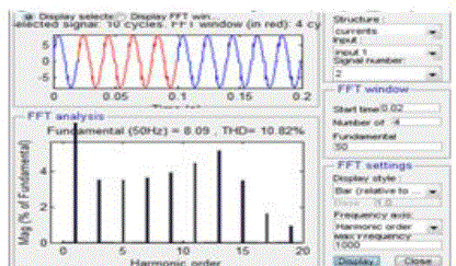
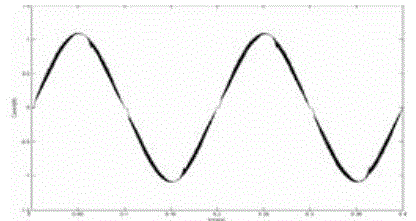
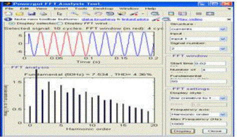
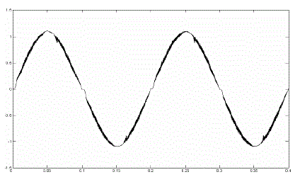
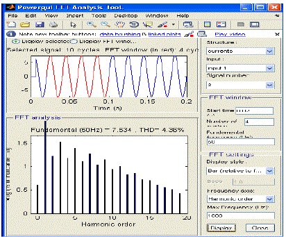
| Selected simulations results on the operation of the proposed hybrid active power filter arrangements are presented. The behaviour of the supply subject to non-linear load is investigated in four modes of operation; without filter, b) with passive filter c) with APF and d) with hybrid. Fig. 8 show results obtained from simulation. I n t h i s p r o j e c t wi t h o u t u s i n g a n y r e c t i f i e r s . The output voltage and currents gets distorted in phase shifts or out of phase.So,the total harmonic distortion values is on the range of 38% to 42%.by connecting simple passive filter half of its means 20% to 24% to reduced.by adding active power filter thd value reduced to 10% to 12%.finally by implementing hybrid active power filter means combination of both active and passive filters the thd value reduced to below 4.36% which is to be economical. |
Comparison:
|
 |
CONCLUSION
|
| This work has illustrated that the single-switch could be used to effective to improve the performance of a passive filter using hybrid APF arrangements that is equally capable of reducing harmonic components in the current supply and achieved unity power factor operation in a single-phase system feeding a non-linear load. Expected sinusoidal supply current that in phase and time with the supply voltage can be obtained by injecting equal but opposite current to shape the pulsating supply current into a sinusoidal form and in time and phase with the supply voltage. The system employs only one control loop to generate appropriate active PWM switching signal, thus minimized the control requirement and reduce switching stress and losses. |
Figures at a glance
|
 |
 |
 |
 |
| Figure 1 |
Figure 2 |
Figure 3 |
Figure 4 |
 |
 |
 |
 |
| Figure 5 |
Figure 6 |
Figure 7 |
Figure 8 |
 |
 |
 |
 |
| Figure 9 |
Figure 10 |
Figure 11 |
Figure 12 |
 |
 |
 |
 |
| Figure 13 |
Figure 14 |
Figure 15 |
Figure 16 |
|
References
|
- J.S. Subjak, JR. and J. S. McQuilkin, “Harmonics-Causes, Effect, Measurementand Analysis: An Update”, IEEE Trans. on Indus. App. Vol. 26, issues , Nov-Dec 1990, pp. 1034-1042.
- M. El-Habrouk, M.K. Darwish and P. Mehta, “Active Power Filter: A Review”, IEEE Proc. Electric power App. Vol.147, Issue 5, Sept. 2000, Page(s):403-413 58..
- M. Ehsani and K.R. Ramani, “Recent advances in power electronics and application”, Southcon Conference Record, March 1994, pp. 8-13.
- B.K. Bose, “Power Electronics-A Technology Review”, Proceeding of IEEE, Vol.80, No.8, Aug. 1992, pp. 1303- 1334.
- Hamzah, N.R.; Hamzah, M.K.; Abu Hasim, A.S.; Abdul Rahman, N.F.A.; “Single-phase shunt active power filter using single-switch incorporating boost circuit”, IEEE 2nd International Power and Energy Conference, 2008. PECon 2008. 1-3 Dec. 2008Page(s):1112 – 1117
- J.H.R Enslin and J.D. Van Wyk, “A New Control Philosophy for Power Electronic Converters as Fictitious Power Compensator” IEEE Transactions on Power Electronics, Vol. 5, No. 1, January 1997.
- J. P. Gegner and C. Q. Lee, “Linear Peak Current Mode Control: A Simple Active Power Factor Correction Control Technique for Continuous Conduction Mode”, 27th Annual IEEE, Power Electronics Specialist Conf. PESC ’96, Vol.1, 23-27 June 1996, pp. 196-202.
- M. F. Siam, “The Control of Static VAR Compensator and Active Power Filter”, Doctorate Thesis, Heriot-Watt University, September 1998.
- A.M. Omar; “The Three-Phase Single Stage Flyback Converter”, Doctor of Philosophy thesis, University of Malaya, Nov. 2001.
|