Keywords
|
| Twophase converters, ZCS, ZVS, Soft Switching converters, PV System, MATLAB. |
INTRODUCTION
|
| Photovoltaic (PV) energy source is a sustainable energy source. They are recyclable, abundant, distributed throughout the earth and pollution free. The hindrance factor is its high installation cost and low conversion efficiency. A proper high efficiency interface is required to transmit the power from PV panel to load. Two phase soft switching boost converter is used as interfacing to reduce the switching loss and ripples [1].In this paper two phase soft switching boost converter is used as power conversion device for photovoltaic system. To increase the output voltage of PV source the two phase boost converter is connected to the PV system.Moreover the input current ripple and stress on power devices are decreased because the input current is divided into two parallel inductors [1]-[7]. Two phase boost converter is used for high power application. |
| The current rating of switching device is reduced by interleaved method which distributes the input current to each phase. It can also reduce input current ripple, output voltage ripple and size of passive components. Soft switching technique is used to reduce the switching loss [8]. The complete system with two phase boost converter is simulated using MATLAB-SIMULINK and the results are presented. The comparative analysis has been made among the two phase converter with uncoupled, directly coupled and inversely coupled inductor for ripple reduction. |
CONFIGURATION OF TWO PHASE BOOST CONVERTER
|
| The conventional two phase boost converter consists of two single boost converters that are connected in parallel as shown in Fig 1. Each switch turns ON with shifting of 360/N. Each inductor current magnitude is decreased by 1/N. The input current ripple is decreased because sum of inductor L1 and L2 are input current [1]. |
| Fig 2 shows the circuit of soft switching two phase boost converter. Switching technique is similar to conventional two phase boost converter. Freewheeling diode, resonant inductor Lr and resonant capacitor Cr are used to soft switching for the reduction of switching loss. And two diodes D1 and D2 are used to transmit energy to output side [1]. |
SYSTEM DESCRIPTION
|
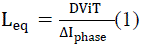
| The two phase boost converter is analysed in this paper. Since it is two phase boost converter each switch has switching gap of 180 degree. Each inductor current repeats linear increment and decrement with 180 degree based on switching pattern. At zero voltage across the resonant capacitor the switch is turned OFF, thus it operate with zero voltage switching (ZVS). At zero current through the resonant inductor the switch is turned ON, thus operate with zero current switching (ZCS) [5].The block diagram in Fig. 3 reveals that the system consists of PV source and two phase boost converter and load and each block is simulated using MatLab and the results are presented. |
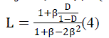
| The interleaved boost converters with coupled inductors are modeled using the following equations [9]-[12].The equivalent value of inductance is given by the expression |
 |
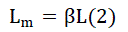
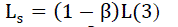
| Self-inductance and mutual inductance are given by |
 |
 Where Where |
 |
| The value of capacitor is given by |
 (5) (5) |
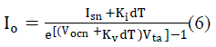
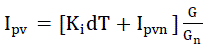
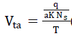
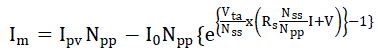
| The PV panel is modeled using one diode model which consists of a current source in parallel with a diode, a shunt resistance and a series resistance as shown in Fig 4. The modeling equations are given through [6] – [9], taken from [13]. |
| The modelling equations are: |
 |
 |
 |
 |
| The simulation results for the system shown in Fig 3 are presented in detail in Section IV. |
SIMULATION RESULTS AND INFERENCE
|
| Using equations (6)-(9), PV panel consists of 36 mono crystalline silicon solar cells have been simulated using MATLAB. The simulated I-V and P-V characteristics are presented in Fig 5. |
| The soft switching two phase boost converter shown in Fig 2 has been simulated with MATLAB. Table I shows the design parameters of the soft switching multi-phase boost converter [1]. |
| Fig. 6 shows the simulation model of two phase boost converter and gating pulse for each switch is shown in Fig 7 and Fig 8. |
| To reduce the input current ripple further, uncoupled inductors L1 and L2 in Fig.2 is replaced by directly coupled and inversely coupled inductors and the comparative analysis have been made among the three types of inductor coupling [14] and the results are presented namely, two phase soft switching converter with uncoupled inductor, directly coupled inductor and inversely coupled inductors. Table II represents the comparative ripple analysis of input current and output voltage in two phase converter and soft switching two phase boost converter. |
| From Table II it is seen that the ripples are reduced in case of soft switching two phase boost converter and the efficiency of the system is also increased. |
| Tables III represents the comparative ripple analysis of input current and output voltage various inductor coupling namely as uncoupled, directly coupled and inversely coupled inductor. |
| From Table III it is understood that ripples have been reduced when directly coupled inductors are used. |
HARDWARE IMPLEMENTATION`
|
| Table IV shows the components that are used to implement the hardware. |
| The pulses for triggering the switches were generated by using PIC18F4550 microcontroller. The gating pulses were given to the devices through an opto-coupler circuit by employing MCT2E opto-coupler to provide the necessary isolation between the power circuit and the microcontroller circuit. The converter was operated using SPV panel as the source. The corresponding outputs were obtained and analyzed to verify the results obtained by simulation with PV panel at the input side. |
| The ripple parameters of input current and output voltage of directly coupled two phase soft switching converter were measured using single phase clamp-on Power Quality Analyzer. The Power Quality Analyzer also gives a measure of the ripple percentage in both the current and voltage on both the input and output sides. It is found that the input current ripple was less compared to other coupling and it is found to be 0.04%.The hardware setup of soft switching two phase boost converter is shown in Fig 9. |
| Fig 10 shows the output voltage and output current waveforms that are observed the DSO. |
| Fig 11 shows the soft switching phenomenon of two phase boost converter. |
CONCLUSION
|
| In this paper, soft switching two phase boost converter for PV system interface has been analysed. Compared to conventional boost converter the input current ripple and output voltage ripple are reduced. Since the converter operates with soft switching principle the switching loss is also reduced and efficiency is high compared with conventional converter. The comparison has been made for different inductor coupling types. It is found that the ripples are further reduced with the use of directly coupled inductors at input side. The hardware implementation of two phase soft switching boost converter has been carried out and the results are presented. |
ACKNOWLEDGMENT
|
| The authors wish to thank the management of SSN College of Engineering, Chennai for providing all the computational facilities to carry out this work. |
Tables at a glance
|
 |
|
|
|
| Table 1 |
Table 2 |
Table 3 |
Table 4 |
|
Figures at a glance
|
 |
 |
 |
 |
| Figure 1 |
Figure 2 |
Figure 3 |
Figure 4 |
 |
 |
 |
 |
| Figure 5 |
Figure 6 |
Figure 7 |
Figure 8 |
 |
 |
 |
| Figure 9 |
Figure 10 |
Figure 11 |
|
References
|
- Gang Yao, Alian Chen and Xianging, “Soft Switching Circuit for Interleaved Boost Converters,” IEEE Transactions on Power Electronics, Vol.22, No. 1, pp.80-86, January 2007.
- .P.Thounthong, P.Sethaku, S.Rael and B.Davat, "Design and implementation of 2- phase interleaved boost converter for fuel cellpower source," in Proc. International Conference on Power Electronics,Machinesand Drives, PEMD 2008, pp. 91-95,2008.
- H.B.Shin, lG.Park, S.K.Chung, HW.Lee and T.A.Lipo, "Generalized Steady-State Analysis of Multiphase Interleaved Boost Converter with Coupled Inductors," in Proc. IEEE Electronics Power Application, Vol.152, No. 3, pp. 584-594,2005.
- P.Lee, Y.Lee, D.KW.Cheng and X.Liu, "Steady-state analysis of an interleaved boost converter with coupled inductors ", IEEE Trans. On Industrial Electronics,Vol. 47, pp. 787-795, 2000.
- Po-Wa Lee, Yim-Shu Lee, David K. W. Cheng, Xiu-Cheng Liu,,“Steady-State Analysis of an Interleaved Boost Converter with Coupled Inductors,” IEEE Transactions on Industrial Electronics,Vol. 47, No. 4, August 2000.
- S. Y. Tseng, J. Z. Shiang, H. H. Chang, W. S. Jwo and C. T. Hsieh,“A Novel Turn-On/Off Snubber for Interleaved Boost Converter,” IEEE 38th Annual Power Electronics Specialists Conference(PESC ’07), pp.2718-2724, 2007.
- H. A. C. Braga and I. Barbi, “A 3-kW unity-power-factor rectifier based on a two-cell boost converter using a new parallel connection technique,” IEEE Transactions on Power Electronics, Vol. 14, No.1, pp.209-217, January 1999.
- Sungsik Park, Yohan Park, Sewan Choi, Woojin Choi, and Kyo-Beum Lee, “Soft-Switched Interleaved Boost Converters for High Step-Up and High-Power Applications,” IEEE Transactions on power electronics, Vol. 26, No. 10, October 2011.
- Doo-Yong Jung, Young-HyokJi, Sang-Hoon Park, Yong-Chae Jung, and Chung-Yuen Won, Senior Member, IEEE “Interleaved Soft- Switching Boost Converter for Photovoltaic Power-Generation System,” IEEE Transactions on Power Electronics, Vol. 26, No. 4, April 2011.
- Doo-Yong Jung, Young-HyokJi, Sang-Hoon Park, Yong-Chae Jung, and Chung-Yuen Won and Yong- chaeJung,”Ripple Analysis Of Interleaved Soft Switching Boost Converter For Photovoltaic Applications”, The 2010 International Power Electronics Conference, 2010
- Sungsik Park.,Yohan Park, Sewan Choi, Woojin Choi and Kyo- Beum Lee, “Soft Switching Interleaved Boost Converter for High Step-up and High Power Applications”, IEEE Transactions on Power Electronics, Vol. 26, No.10, October 2011.
- R.N.A.L.Silva,G.A.L.Henn,P.P.Praca, L.H.S.C.Barreto, D.S.Oliveira,Jr., and F.L.M.Antunes,” Soft Switching Interleaved Boost converter with High Voltage Gain”, IEEE Transactions on Power Electronics, Spec.Conf(PESC),pp 4157-4161,June 2008.
- R.Ramaprabha and B.L.Mathur, “MATLAB based Modelling and Performance study of Series Connected SPVA under under Partial Shaded conditions,” Journal of Sustainable Development, Vol 2, No.3, pp 85-94, Nov 2009.
- G. Ramya and R.Ramaprabha, “Comparative Analysis of Soft Switching Two-Phase Boost Converter for Photovoltaic System”, presented in IEEE International Conference on Circuit, Power and Computing Technologies (ICCPCT 2013) ,pp. 231-235 , March 2013.
- www.mathworks.com
|