INTRODUCTION
|
| A thermal power station is a power plant in which the prime mover is steam driven. Water is heated, turns into steam and spins a steam turbine which drives an electrical generator. After it passes through the turbine, the steam is condensed in a condenser and recycled to where it was heated; this is known as a Ranking cycle. The greatest variation in the design of thermal power stations is due to the different fossil fuel resources generally used to heat the water. Some prefer to use the term energy center because such facilities convert forms of heat energy into electrical energy. Certain thermal power plants also are designed to produce heat energy for industrial purposes of district heating, or desalination of water, in addition to generating electrical power. Globally, fossil fueled thermal power plants produce a large part of man-made CO2 emissions to the atmosphere, and efforts to reduce these are varied and widespread. |
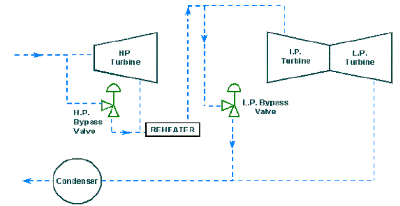
| During startup, shutdown and load disturbances in a power plant, the boiler (HRSG in combined cycle designs) and steam turbine need to be isolated from one another. This is to protect the turbine from any water carry over, but also protect additional plant equipment from large thermal transients. By isolating the boiler and steam turbine it is also possible to reduce fuel consumption during startup and shutdown. In the event of a load rejection, reloading times can also be improved through the turbine bypass system. The turbine bypass system is designed to provide the quickest startup time by controlling both boiler pressure and temperature. Bypassing the steam around the turbine allows the steam to attain the desired qualities before being routed through the turbine. If the turbine bypass system were not used, the firing rate of the boiler would have to be reduced, which could lead to tube failures. The bypass system allows the boiler to be fired at full capability without introducing large thermal gradients in the thick walled components such as the boiler drum and any separators or flash tanks. In order to protect the reheater tube banks from overheating, the high pressure steam is routed around the high pressure turbine into the cold reheat piping. The steam flows through the reheater tube banks and is then routed through the low pressure turbine bypass valve to the condenser. This type of arrangement ensures that the boiler can remain in operation during a load rejection, which keeps the safety valves from lifting, and keeps other equipment from tripping allowing immediate reloading of the turbine [2]. |
II. IMPORTANCE of BYPASS VALVE
|
| In conventional units and combined cycle units without hot reheat bypass valves, the low pressure valve must be able to bypass the entire unit mass flow in the case of an upset. Also, the temperature of the steam must be reduced to near saturated conditions to limit the size of the condenser and prevent thermal fatigue due to high temperatures. One of the main concerns in this application is the noise generated when the pressure is let down from the low pressure section (75 - 200 kg/cm2) to the condenser, which is under vacuum (2 – 5 kg/cm2). The noise generated can cause vibration that can damage the downstream equipment [1]. Another concern is temperature control. Inlet temperatures to the valve vary between 400 and 600 degrees and must be dropped to near saturated conditions at the valve outlet. This is necessary to facilitate heat transfer in the condenser while protecting the condenser from thermal fatigue. For the best efficiencies and overall plant heat rate, tight shutoff is recommended. If the bypass valve leaks, steam that could be driving the turbine will be lost to the condenser. Because of the pressures and the large amount of flow involved, poor shutoff will lead to significant valve damage in a relatively short amount of time. |
| There are several possible solutions to address this application. The most common device used is called a turbine bypass valve that combines both pressure and temperature reduction into one control valve. The valve controls the flowing pressure drop the same as any control valve, but controls the temperature via a spray water section at the exit of the valve. This spray water section can either be attached to the valve or some distance downstream. Another alternative is a separate pressure reducing valve and a separate desuperheater downstream from the valve. This arrangement works well when installation flexibility is a consideration. The downside is that if the valve and desuperheater are separated a dead time or lag can be introduced into the system because of the distance between the pressure reducing valve and downstream cooling section [2]. This turbine bypass valve incorporates both pressure and temperature control into one valve body. The valve is |
| designed to withstand the thermal transients typical in this application. Extensive research into thermal mixing of water and steam ensuring the best spray patterns and nozzle designs [3]. For applications where installation flexibility is required, the design with a downstream cooler or desuperheater is recommended. Noise abatement trim can be installed into the control valves to eliminate any damaging noise and vibration. The same type of cooler design can be installed a given distance downstream of the pressure reducing valve to provide the proper temperature control. Fast acting actuation is required to protect the steam turbine during the event of a load rejection with most requirements ranging between one and two seconds [7]. The pneumatic actuation system with the booster arrangement will meet stroking requirements of one to two seconds. In applications where faster acting times are required, electro-hydraulic actuation packages are available. |
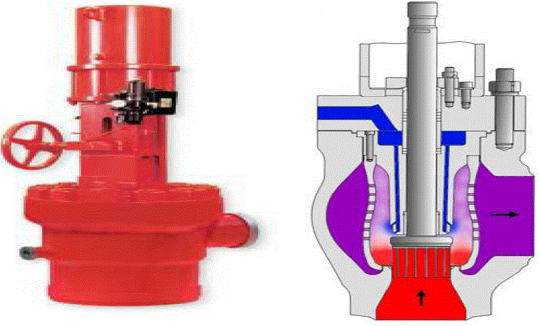
| In these internal and external view of a high pressure bypass valve arrangement is shown in (fig 2), the valve has a control for opening and closing of the bypass valve is shown in external view and in the internal view shows the temperature reduction between the steam entering and moving out from the bypass valve, the spray water tubes helps the bypass valve to reduce the temperature of the steam in the bypass valve [6]. |
A. Desuperheater
|
| In the desuperheater, the cooling water enters the venturi through a special streamlined spray nozzle. On the surface of this spray nozzle a thin film of the water will be formed. The dynamic energy of the incoming steam flow breaks the surface tension of the film, creating a conical shaped spray (at slightly lower pressure) of atomized cooling water. Correct mixing is attained by the turbulence of the steam flow, which is caused by the interaction of the venturi effect and the specially shaped spray nozzle. The result is rapid and total evaporation of the cooling water. As consequence, optimal and swift temperature control adjustments are possible. This also avoids the need for any protective liners in downstream piping [8][9]. |
III.CONTROL STATION
|
| The function of HPBP System is to bypass the steam from boiler drum to the Intermediate Pressure Turbine over High Pressure Turbine. This system is keep-on watching the differential pressure between the boiler drum and steam entering in the HP Turbine (HPT). If the rate of change differential pressure is more than 18 kg/cm2, this system come out of automatic mode and let the last turbine pressure is a set point, against set point, excess steam is bypassed through HPBP System. When process back to normally, manually it has to be matched and switched to automatic mode. |
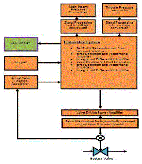
| In the block diagram (fig 3) the main stream pressure is the main pressure from the boiler i.e. the steam which is superheated by the flue gases and it is pressure is sensed by the pressure sensor, the throttle pressure is the pressure in the turbine control valve which is also sensed by the pressure sensor and the signal conditioner converts that current into voltage these analog valve is fed to the ADC pins in the microcontroller these ADC valve are compared in the microcontroller if the differential pressure between the main stream pressure and the control valve pressure is more than the 18 kg/cm2 then the bypass valve opens if it is less than the differential pressure then the bypass valve close until the pressure valve is equal to the set point valve, it is the differential pressure set by the system depends on the last turbine control valve i.e. before fault, the keypad allows the user to set the set point valve and the LCD display shows the pressure in both valves , differential pressure valves , and also the status of the bypass valve processes i.e. opening or closing. The servo mechanism based hydraulic power driving amplifier opens or closes the bypass valve depends on the control from the microcontroller. |
A. EXECUTION
|
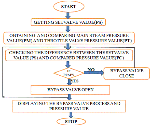
| Once the process is started, set valve value (PS) will be assigned. Then the value of main stream pressure value (PM) and throttle valve pressure value (PT) will be compared and its difference value will be known as compared pressure value (PC). If PC value is greater than PS value, then PC is less than PS, then bypass valve will close. The value of pressure and position of the valve will be displayed. Once the PC becomes equal to PS then process will be stopped is shown in the (fig 4). |
V. SIMULATION
|
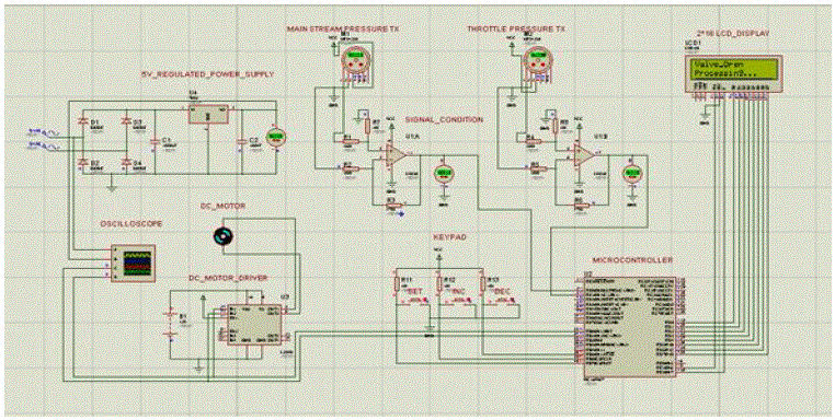
| The boiler drum pressure and control valve pressure is sensed by using the pressure sensor, the signal from the sensor is converted to the voltage by using signal conditioner, these converter gives analog signal to the microcontroller, analog to digital converter in microcontroller converts them into digital signals by using that digital signals, used to control the valve driving amplifier of dc motor. Depending upon the digital signal dc motor rotates in either forward direction or in reverse direction, these achieved with the help of driver circuit. |
VI. CONCLUSION
|
| The main reason for installing turbine bypass systems is improving flexibility in plant operation, especially during startup, shutdown and disturbed plant operation. Benefits of this enhanced flexibility are faster startup times, reduced downtime, and higher availability of the plant, resulting in less fuel costs and lower overall plant-operating costs. These desired results are only achievable when all components are designed and selected to suit the specific needs of a bypass system, and all components are well-matched. This is achieved when the whole system-valves, actuators, and controls are in the design and operation of bypass systems and the ability to integrate all components. |
| |
Figures at a glance
|
 |
 |
 |
 |
 |
| Figure 1 |
Figure 2 |
Figure 3 |
Figure 4 |
Figure 5 |
|
| |
References
|
- Bypass Systems Designed to Improve Efficiency and Flexibility of Thermal Power Plants by Ulrich Kägi
- R. Rohner, Sulzer Bypass-Systems for Fossil Power Stations Mech E Power Conference
- Getting Reliable Turbine Bypass System Performance in Cycling Power Plants Ron Adams, CCI; Ulrich Kaegi, CCI; and Sanjay Sherikar, CCI
- Guy Borden, Jr., and Paul G. Friedmann, Control Valves – ISA Practical Guides for Measurement and Control, International Society of Measurementand Control, Research Triangle Park, N. C., 1998.
- H. L. Miller, and L. R. Stratton, “Fluid Kinetic Energy as a Selection Criterion for Control Valves,” Paper No. FEDSM97-3464, presented at theAmerican Society of Mechanical Engineers, Fluids Engineering Division Summer Meeting, Vancouver, British Columbia, June 22-26, 1997.
- Sherikar, S.V. and Borzsony, P., Advances in Desuperheating Technology for Reliable Performance o f Combined Cycle Power Plants (CCCP), PaperPWR 2005-50108, ASME Power Conference, Chicago, Illinois, April 5-7, 2005.
- Anderson, Robert W., and Ballegooyan, Hank van, Steam Turbine Bypass Systems, Combined Cycle Journal, pp. 3-9, Fourth Quarter Journal, 2003.
- Rohner, R., Blumer, U. and Aregger, J., Contributions of Bypass Systems to the Flexibility of Advanced Steam Plants, Advanced Steam PlantsConference, I. Mech. E., London, May 21-22, 1997.
- Swanekamp, Robert, Combined Cycle Plants Broaden Their View to Integrated Plants, Power Engineering, pp. 36-42, July 2004
|