Keywords
|
| Z source inverter, reduced voltage stress, soft start strategy, induction motor. |
| |
| |
INTRODUCTION
|
| The Z source inverter [2] is a single stage converter that can either buck or boost the ac output voltage from a dc supply. This topology overcomes the shortcomings of the traditional voltage source and current source inverters, where the output ac voltage is either respectively less or more than the input dc voltage. This combined operation of the z source inverter eliminates the need of a separate dc-dc converter, thus reducing the cost and increasing the efficiency of the circuit. |
| Z source inverter also allows two switches of the same leg to be gated in the circuit, thus eliminating the shoot through fault that occurs in traditional converters. This feature of the inverter provides the elimination of dead time in the circuit, thus increasing the reliability and reducing the output distortion of the inverter. Saying that does not free the Z source inverter from few of its operating problems - the voltage across the capacitors in the traditional Z source inverter is equal to the input voltage which increases the volume and cost of the capacitors used; and also the startup current and voltage in the circuit is very much higher which may destroy the devices at one time or the other. |
| So to overcome the abovesaid problems, a new topology of the Z source inverter is used, that can be used to drive an induction motor and to control its operating speed. |
II. Z SOURCE INVERTER
|
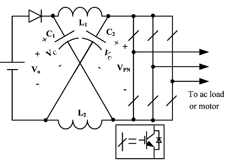
| An unique impedance network is used in the Z source inverter that consists of two identical inductors L1 and L2 alongwith two identical capacitors C1 and C2 that couples the power supply circuit to the inverter circuit. The shoot through period i.e., the time period when two switches of the same leg are gated allows the voltage to be boosted to the required value when the input dc voltage is not upto the required level. Else otherwise, the shoot through state is not used thus enabling the ZSI to operate as both a buck-boost inverter unlike the traditional voltage source and the current source inverters. |
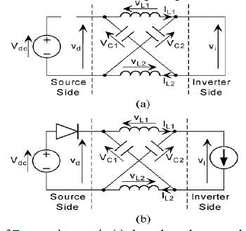
| The above figure shows the presence of the z source impedance network preceding the inverter main circuit. The diode is used to prevent the reverse flow of current in the circuit. Fig 2a&2b represent the equivalent circuit of the Z source network in shoot through and non shoot through states respectively. The energy is stored in the inductors in the shoot through state when both the switches on the same leg of the inverter are gated. This energy is then transferred in addition to the supply voltage to the load side when normal gating of the inverter switches occur. |
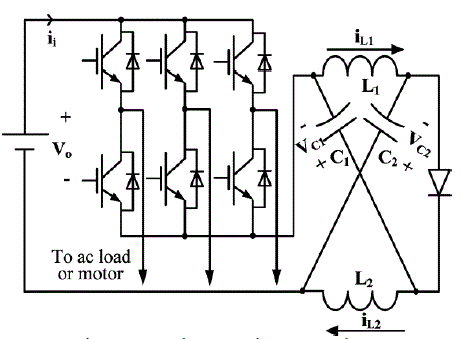
| The following figure shows the proposed Z source inverter [1] wherein the impedance network succeeds the inverter circuit. |
| The merits of the new topology are : |
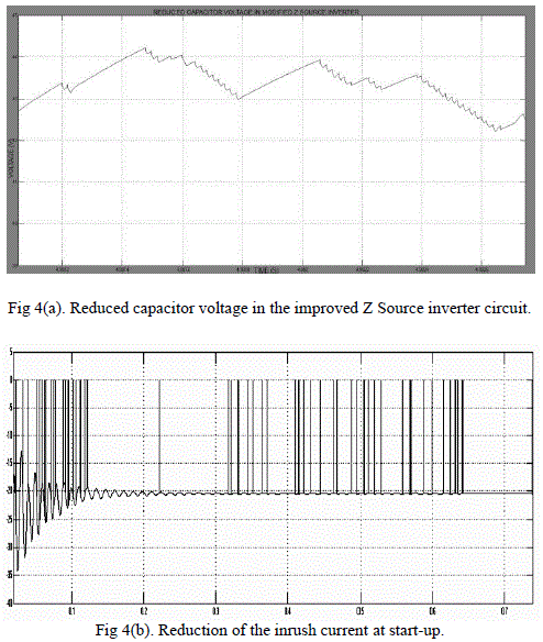
| 1. The voltage polarity of the capacitor s remain the same providing similar voltage boost capability, but with reduced voltage stress across them as shown in Fig 4(a). |
| 2. The inrush current at startup is effectively reduced since there is no path for current at start-up. |
| The current and the voltage ripples in both the topologies remain the same, whereas the current across the inductor in the existing topology decreases in the non shoot through state. In the existing topology, the voltage across the capacitors is given by |
 |
| And in the new topology, it is given as |
 |
| where Vc = capacitor voltage; D = duty ratio of the shoot through state; and Vs = supply voltage. |
| The above equations show that the capacitor voltage is equal to the supply voltage when D=0 in the existing circuit, and in the new model it is reduced to zero when D=0. This proves that the capacitor voltage is greatly reduced and provides for a soft start strategy in the new topology. |
| The pulse width modulation of the Z Source inverters [3] produces the ac voltage boost by controlling the duty cycle of the switches used in the circuit. The ability of the Z Source system to produce any desired ac output voltage, |
| provide ride through conditions during voltage sags and to minimize the motor ratings to produce the required power enables it to be used for adjustable speed drive systems [4]. |
III. INDUCTION MOTOR
|
| Three phase induction motors are the most widely used in various industrial applications because of the following properties - self starting property; elimination of a starting device; robust construction; higher power factor and good speed regulation. But the induction motor is a constant speed machine which makes its applications pretty much limited. To increase the areas of application of the induction motor, its speed has to be controlled by varying the supply frequency. The advantage of speed control of the induction machine is that it can save the energy spent by the machine. For example, a speed reduction of about 20% can improve the energy savings upto 50% in a centrifugal pump. This means that an energy inefficient motor can be replaced by a variable speed machine given an efficient control system. |
| The base speed of an induction motor is directly proportional to the supply frequency and the number of poles. Now since the number of poles is fixed in the motor design, the best way to control the speed of the motor is to vary the supply frequency. The torque developed by the motor is directly proportional to the ratio of the applied voltage and the supply frequency. The torque is kept constant by varying the applied voltage and the supply frequency and by keeping their ratio to a constant value. |
| The torque speed characteristics also denote that : |
| 1. The starting current requirement is lower. |
| 2. The stable operating point of the motor is increased. The motor can be run at 5% of the synchronous speed upto base speed instead of running the motor from the base speed itself. |
| 3. The acceleration and deceleration of the motor can be controlled by controlling the change of the supply frequency of the motor with respect to time. |
| The open loop Volts/Hz control of an induction motor is far the most popular method of speed control because of its simplicity and these types of motors are widely used in industry. Traditionally, induction motors have been used with open loop 60Hz power supplies for constant speed applications. For adjustable speed applications, frequency control is natural. However, voltage is required to be proportional to frequency so that the stator flux remains constant if the stator resistance is neglected. |
| In an outer loop controlled induction motor drive, the actual rotor speed is compared with its commanded value, and the error is processed through a controller usually a PI controller and a limiter are used to obtain the slip-speed command. The limiter ensures that the slip-speed command is within the maximum allowable slip-speed of the induction motor. The slip-speed command is added to electrical rotor speed to obtain the stator frequency command. Thereafter the stator frequency command is processed as in an open loop drive. In the closed loop induction motor drive the limits on the slip speed, boost voltage and reference speed are externally adjustable variables. The external adjustment allows the tuning and matching of the induction motor to the converter and inverter and the tailoring of its characteristics to match the load requirements. |
IV. CIRCUIT AND SIMULATION
|
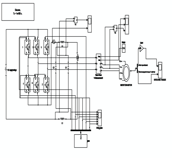
| The three phase induction motor is connected to the three inverter bridge whose 6 switches are controlled in order three phase ac output from the dc bus. PWM signals generated from a microcontroller are used to control the 6 switches. The DC bus voltage in this case is increased or decreased to the required value by the improved version of the z source inverter. The higher value of the dc voltage is obtained when the value of the inductance in the circuit is increased. Likewise, the dc voltage is decreased by increasing the value of the capacitance in the circuit, thereby providing buck/boost functionality to the circuit. And also the Z source inverter allows both the switches in the same phase leg to be gated at the same time without producing any damage to the switches. This negates the presence of any dead time in the circuit, and actually helps in the buck/boost performance of the improved ZSI by controlling the duty cycle of the shoot through state. |
| The amplitude of the phase voltage is dependent on the duty cycle of the PWM signals given to the inverter switches. At any instant of time, 3 switches (2 upper and1 lower or 1 upper and 2 lower) are gated and the remaining 3 are turned OFF. The switching produces a rectangular shaped output waveform that is rich in harmonics. The supplied current with harmonics is made to produce 3-phase sine wave with negligible harmonics by the inductive nature of the motor’s stator windings. The inductive nature of the windings oppose any sudden change in the reverse direction of flow of current until all of the energy stored in the windings are dissipated, when the switches are turned off. This is accomplished using fast recovery diodes, known as freewheeling diodes across every Insulated-Gate Bipolar Transistor (IGBT) switch. |
| Figure 5(a) show the simulation of the open loop operation of the induction motor using MATLAB program. The simulation results prove that the motor has a high starting torque and does not require any separate starting circuit unlike a few other motors. The motor block used in the simulation is the squirrel cage induction motor block which is a commonly used induction motor type. The rotor bars are permanently shorted in this motor, thus negating the addition of any external resistance to the motor circuit. |
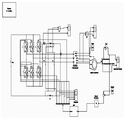
| Thus the rotor copper losses are reduced, thus providing higher efficiency. Figure 5(b) shows the simulation of the closed loop operation of the induction motor in which the motor’s actual running speed is compared with a base speed, in this case 1200 rpm. |
| The values of the various components used in the circuit are : Inductors L1 = L2 = 1mH; Capacitors C1 and C2 used are 13300μF; the induction motor parameters are given as 6 pole, 1200 rpm, 60Hz, 50 HP machine. |
| The error between the actual running speed of the motor and the reference value is calculated and the control mechanism is executed by using a PI controller in this case. |
| The control signal is then given to a PWM generator which then produces the required gating signals that are to be given the 6 IGBT switches. The switches act according to the gate pulses given to them and the speed of the motor is controlled to the required value. The function of the proportional term of the PI controller is to consider the current size of the error value only at the time of controller calculation, and the integral term of the PI controller eliminates offset and sums up the complete controller error history up to the present time, starting from when the controller was first switched to automatic. |
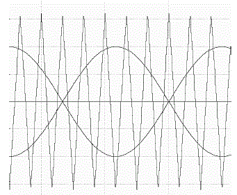
| Sinusoidal pulse width modulation as shown in Fig 6. is employed in the circuit to turn on the switches. The extent, to which the dc voltage is boosted via the Z source network i.e. the boost factor, is decided by the modulation index of the pulse width modulation used. |
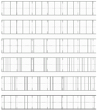
| The switches 1,4 are simultaneously gated in the following figure (Fig 7) to provide the shoot through condition for the inverter. This enables the voltage to be increased to the required value without the additional need of switches like in the case of conventional buck/boost converters. The shoot through condition is also used to buck the voltage given to the load side via proper gating signals thus providing a dual buck/boost function using the same Z source inverter circuit. |
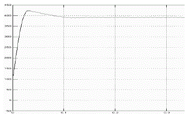
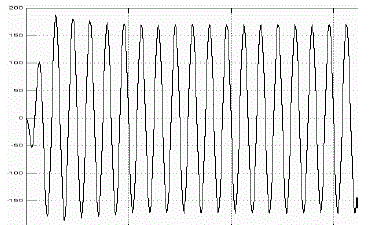
| The input dc voltage of 230V is boosted to a higher value of 393V in this circuit and then converted to an equal value of ac voltage via the inverter, which has been depicted in Fig 8 and Fig 9 respectively. |
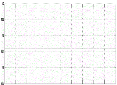
| Now the inverter output voltage is used to drive the three phase induction motor whose speed is to be adjusted according to the required preset value. Fig 10 shows the closed loop controlled simulation of the induction motor with the speed running at a constant preset value. |
V. APPLICATIONS
|
| The improved ZSI can be applied to areas where the input DC voltage is unreliable or it is of highly varying in nature, thus making it useful in non conventional sources of energy such as in photovoltaic systems and in fuel cell applications in which the DC voltage can be boosted to the required value. The speed control feature of the induction motor is highly efficient and can be used a number of adjustable speed applications. |
VI. CONCLUSION
|
| This paper has presented a new Z source inverter topology to control the speed of a three phase induction motor. The topology has the following merits. |
| 1. The Z source capacitor voltage stress is reduced greatly to perform the same voltage boost, thus enabling lowvoltage capacitors to be used to reduce the system cost and volume. |
| 2. The inrush current is suppressed and the traditional topology can be started off with a soft start capability. |
| 3. The PI controller enables the control of the speed of the induction motor, thus providing with a constant speed application that can be used in various forms. |
| |
| |
Figures at a glance
|
 |
 |
 |
 |
| Figure 1 |
Figure 2 |
Figure 3 |
Figure 4 |
 |
 |
 |
 |
| Figure 5a |
Figure 5b |
Figure 6 |
Figure 7 |
 |
 |
 |
| Figure 8 |
Figure 9 |
Figure 10 |
|
| |
References
|
- Yu Tang, Member, IEEE, Shaojun Xie, Member, IEEE, and Chaohua Zhang “An improved Z Source Inverter”, IEEE Trans. Pow.Elec, vol. 26, no. 12, pp. 3865-3868, Dec 2011.
- F. Z. Peng, “Z-source inverter,” IEEE Trans. Ind. Appl., vol. 39, no. 2, pp. 504–510, Mar./Apr. 2003.
- P. C. Loh, D. M. Vilathgamuwa, Y. S. Lai, G. T. Chua, and Y. Li, “Pulse-width modulation of Z-source inverters,”IEEE Trans. Power Electron., vol. 20, no. 6, pp. 1346–1355, Nov. 2005..
- F. Z. Peng, A. Joseph, J. Wang, M. Shen, L. Chen, Z. Pan, E. O. Rivera, and Y. Huang, “Z-source inverter for motor drives,” IEEE Trans.Power Electron., vol. 20, no. 4, pp. 857–863, Jul. 2005.
|