Keywords
|
| Noise Representation ,PSNR , Transformation ,Gaussian noise |
INTRODUCTION
|
| Peak signal-to-noise ratio, often abbreviated PSNR, is an engineering term for the ratio between the maximum possible power of a signal and the power of corrupting noise that affects the fidelity of its representation. Because many signals have a very wide dynamic range, PSNR is usually expressed in terms of the logarithmic decibel scale.PSNR is most commonly used to measure the quality of reconstruction of lossy compression codecs (e.g., for image compression). The signal in this case is the original data, and the noise is the error introduced by compression. When comparing compression codecs, PSNR is an approximation to human perception of reconstruction quality. Although a higher PSNR generally indicates that the reconstruction is of higher quality, in some cases it may not. One has to be extremely careful with the range of validity of this metric; it is only conclusively valid when it is used to compare results from the same codec (or codec type) and same content. PSNR is most easily defined via the mean squared error (MSE). Given a noise-free m×n monochrome image I and its noisy approximation K, MSE is defined as: |
 |
| The PSNR is defined as: |
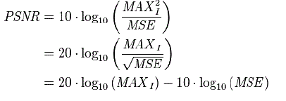 |
| `Here, MAXI is the maximum possible pixel value of the image. When the pixels are represented using 8 bits per sample, this is 255. More generally, when samples are represented using linear PCM with B bits per sample, MAXI is 2B−1. For color images with three RGB values per pixel, the definition of PSNR is the same except the MSE is the sum over all squared value differences divided by image size and by three. Alternately, for color images the image is converted to a different color space and PSNR is reported against each channel of that color space, e.g., YCbCr or HSL |
| Typical values for the PSNR in lossy image and video compression are between 30 and 50 dB, where higher is better. Acceptable values for wireless transmission quality loss are considered to be about 20 dB to 25 dB. In the absence of noise, the two images I and K are identical, and thus the MSE is zero. In this case the PSNR is undefined (see Division by zero). |
 |
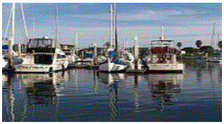
| Q=90, PSNR 45.53dB |
 |
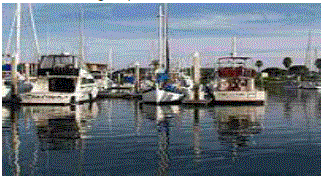
| Q=30, PSNR 36.81dB |
 |
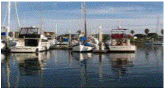
| Q=10, PSNR 31.45dB |
 |
| Original uncompressed image |
DESIGN METHODS FOR THE IMAGE REPRESENTATION
|
| Simulink blocks used for the representation are as follows |
| 1. FROM MULTIMEDIA FILE BLOCK:This block is present in the Computer system vision toolbox and dsp system toolbox. The From Multimedia File block reads audio samples, video frames, or both from a multimedia file. The block imports data from the file into a Simulink model. |
| This block supports code generation for the host computer that has file I/O available. You cannot use this block with Real-Time Windows Target software because that product does not support file I/O. The generated code for this block relies on prebuilt library files. We can run this code outside the MATLAB environment, or redeploy it, but be sure to account for these extra library files when doing so. The packNGo function creates a single zip file containing all of the pieces required to run or rebuild this code. To run an executable file that was generated from a model containing this block, we may need to add precompiled shared library files to your system path. |
| 2. VIDEO VIEWER: The Video Viewer block enables you to view a binary, intensity, or RGB image or a video stream. The block provides simulation controls for play, pause, and step while running the model. The block also provides pixel region analysis tools. During code generation, Simulink Coder software does not generate code for this block. The To Video Display block supports code generation. Setting Viewer Configuration The Video Viewer Configuration preferences enables you to change the behavior and appearance of the graphic user interface (GUI) as well as the behavior of the playback shortcut keys. |
Core Pane
|
| The Core pane in the Viewer Configuration dialog box controls the GUI's general settings. If you select the Display the full source path in the title bar check box, the GUI displays the model name and full Simulink path to the video data source in the title bar. Otherwise, it displays a shortened name.Use the Open message log: parameter to control when the Message log window opens. You can use this window to debug issues with video playback. Your choices are for any new messages, for warn/fail messages, only for fail messages, or manually. |
Tools Pane
|
| The Tools pane in the Viewer Configuration dialog box contains the tools that appear on the Video Viewer GUI. Select the Enabled check box next to the tool name to specify which tools to include on the GUI. |
Image Tool
|
| Click Image Tool, and then click the Options button to open the Image Tool Options dialog box.Select the Open new Image Tool window for export check box if you want to open a new Image Tool for each exported frame. |
Pixel Region
|
| Select the Pixel Region check box to display and enable the pixel region GUI button. For more information on working with pixel regions see Getting Information about the Pixels in an Image. |
Image Navigation Tools
|
| Select the Image Navigation Tools check box to enable the pan-and-zoom GUI button. Instrumentation Set Select the Instrumentation Set check box to enable the option to load and save viewer settings. The option appears in the File menu. |
Video Information
|
| The Video Information dialog box lets you view basic information about the video. To open this dialog box, you can select Tools > Video Information , click the information button , or press the V key. Colormap for Intensity Video The Colormap dialog box lets you change the colormap of an intensity video. You cannot access the parameters on this dialog box when the GUI displays an RGB video signal. |
| Use the Colormap parameter to specify the colormap to apply to the intensity video.If you know that the pixel values do not use the entire data type range, you can select the Specify range of displayed pixel values check box and enter the range for your data. The dialog box automatically displays the range based on the data type of the pixel values. |
Status Bar
|
| A status bar appear along the bottom of the Video Viewer. It displays information pertaining to the video status (running, paused or ready), type of video (Intensity or RGB) and video time. |
Message Log
|
| The Message Log dialog provides a system level record of configurations and extensions used. You can filter what messages to display by Type and Category, view the records, and display record details. The Type parameter allows you to select either All, Info, Warn, or Fail message logs. The Category parameter allows you to select either Configuration or Extension message summaries. The Configuration messages indicate when a new configuration file is loaded. The Extension messages indicate a component is registered. For example, you might see a Simulink message, which indicates the component is registered and available for configuration.Saving the Settings of Multiple Video Viewer GUIs.The Video Viewer GUI enables you to save and load the settings of multiple GUI instances. Thus, you only need to configure the Video Viewer GUIs . |
AWGN CHANNEL:
|
| The AWGN Channel block adds white Gaussian noise to a real or complex input signal. When the input signal is real, this block adds real Gaussian noise and produces a real output signal. When the input signal is complex, this block adds complex Gaussian noise and produces a complex output signal. This block inherits its sample time from the input signal. This block accepts a scalar-valued, vector, or matrix input signal with a data type of type single or double. The output signal inherits port data types from the signals that drive the block. All values of power assume a nominal impedance of 1 ohm |
Signal Processing and Input Dimensions
|
| This block can process multichannel signals. When you set the Input Processing parameter to Columns as channels (frame based), the block accepts an M-by-N input signal. M specifies the number of samples per channel and N specifies the number of channels. Both M and N can be equal to 1. The block adds frames of length-M Gaussian noise to each of the N channels, using a distinct random distribution per channel. |
Specifying the Variance Directly or Indirectly
|
| You can specify the variance of the noise generated by the AWGN Channel block using one of these modes: Signal to noise ratio (Eb/No), where the block calculates the variance from these quantities that you specify in the dialog box: |
| Eb/No, the ratio of bit energy to noise power spectral density |
| Number of bits per symbol |
| Input signal power, the actual power of the symbols at the input of the block Symbol period Signal to noise ratio (Es/No), where the block calculates the variance from these quantities that you specify in the dialog box: |
| Es/No, the ratio of signal energy to noise power spectral density |
| Input signal power, the actual power of the symbols at the input of the block |
Symbol period
|
| Signal to noise ratio (SNR), where the block calculates the variance from these quantities that you specify in the dialog box: |
| SNR, the ratio of signal power to noise power |
| Input signal power, the actual power of the samples at the input of the block |
| Variance from mask, where you specify the variance in the dialog box. The value must be positive. Variance from port, where you provide the variance as an input to the block. The variance input must be positive, and its sampling rate must equal that of the input signal. Changing the symbol period in the AWGN Channel block affects the variance of the noise added per sample, which also causes a change in the final error rate. |
| A good rule of thumb for selecting the Symbol period value is to set it to be what you model as the symbol period in the model. The value would depend upon what constitutes a symbol and what the oversampling applied to it is (e.g., a symbol could have 3 bits and be oversampled by 4). |
| In both Variance from mask mode and Variance from port mode, these rules describe how the block interprets the variance: |
| If the variance is a scalar, then all signal channels are uncorrelated but share the same variance. If the variance is a vector whose length is the number of channels in the input signal, then each element represents the variance of the corresponding signal channel. If you apply complex input signals to the AWGN Channel block, then it adds complex zero-mean Gaussian noise with the calculated or specified variance. The variance of each of the quadrature components of the complex noise is half of the calculated or specified value. |
RELATIONSHIP AMONG EB/NO, ES/NO, AND SNR MODES
|
| For complex input signals, the AWGN Channel block relates Eb/N0, Es/N0, and SNR according to the following equations: |
| Es/N0 = (Tsym/Tsamp) · SNR |
| Es/N0 = Eb/N0 + 10log10(k) in dB |
| where |
| Es = Signal energy (Joules) |
| Eb = Bit energy (Joules) |
| N0 = Noise power spectral density (Watts/Hz) |
| Tsym is the Symbol period parameter of the block in Es/No mode |
| k is the number of information bits per input symbol |
| Tsamp is the inherited sample time of the block, in seconds |
| For real signal inputs, the AWGN Channel block relates Es/N0 and SNR according to the following equation: Es/N0 = 0.5 (Tsym/Tsamp) · SNR |
| that the equation for the real case differs from the corresponding equation for the complex case by a factor of 2. This is so because the block uses a noise power spectral density of N0/2 Watts/Hz for real input signals, versus N0 Watts/Hz for complex signals. |
SIMULINK MODEL
|
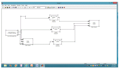
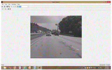
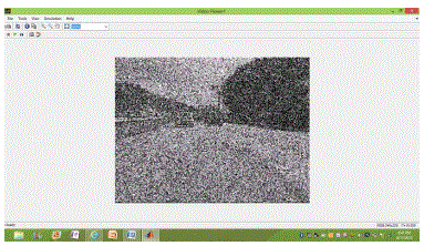
| The original image and the noise representation in the model is represented below: |
 |
 |
 |
CONCLUSION
|
| Image processing basically includes the following three steps. Importing the image with optical scanner or by digital photography. Analyzing and manipulating the image which includes data compression and image enhancement and spotting patterns that are not to human eyes like satellite photographs. Output is the last stage in which result can be altered image or report that is based on image analysis. |
Purpose of Image processing
|
| The purpose of image processing is divided into 5 groups. They are: |
| 1. Visualization - Observe the objects that are not visible. |
| 2. Image sharpening and restoration - To create a better image. |
| 3. Image retrieval - Seek for the image of interest. |
| 4. Measurement of pattern – Measures various objects in an image. |
| 5. Image Recognition – Distinguish the objects in an image. |
Types
|
| The two types of methods used for Image Processing are Analog and Digital Image Processing. Analog or visual techniques of image processing can be used for the hard copies like printouts and photographs. Image analysts use various fundamentals of interpretation while using these visual techniques. The image processing is not just confined to area that has to be studied but on knowledge of analyst. Association is another important tool in image processing through visual techniques. So analysts apply a combination of personal knowledge and collateral data to image processing. |
| Digital Processing techniques help in manipulation of the digital images by using computers. As raw data from imaging sensors from satellite platform contains deficiencies. To get over such flaws and to get originality of information, it has to undergo various phases of processing. The three general phases that all types of data have to undergo while using digital technique are Pre- processing, enhancement and display, information extraction |
 |
References
|
- J. F. Lichtenauer,M. J. T. Reinders, E. A. Hendriks. A Hybrid Approach to Sign Language Recognition, The 20th Belgian-NetherlandsConference on Artificial Intelligence, University of Twente, Enschede, the Netherlands, October 30-31, 2012.
- J. F. Lichtenauer, M. J. T. Reinders, E. A. Hendriks. Learning to Recognize a Sign from a Single Example, In proceedings of the 8thIEEE International Conference on Face and Gesture Recognition, Amsterdam, The Netherlands, September 2012.
- Spaai, E. A. HendriksandM. J. T. Reinders. Sign Language Recognition by combining Statistical DTWand IndependentClassification, IEEE Trans.Pattern Analysis and Machine Intelligence, vol. 30 (11), pp. 2040-2046,Nov2012
- Kulkarni , C. Fortgens, M. Elzenaar, E. Wenners, J. Lichtenauer, E. Hendriks,H. de Ridder, J. Arendsen, G. ten Holt Eencomputerprogrammavoor het leren van actieve en passievegebarenschataanernstigslechthorende en dovekinderen,Logopedie en Foniatrie, vol. 80 (2), February 2013.
- Hasan, I. Setyawan, T. Kalker and R. L. Lagendijk. Exhaustive Geometrical Search and the False Positive WatermarkDetection Probability, In Proceedings of SPIE, Security, Steganography and Watermarking of MultimediaContents V, vol. 5020, pp. 203-214, Santa Clara, USA, January 20-24 2003.
- Eng-Jon Ong and Richard Bowden, “A boosted classifier tree for hand shape detection,” in Proceedings of Int. Conf. on Automatic Face and Gesture Recognition. Seoul, Korea, May 2011, pp. 889 – 894.
- Mathias Kolsch and Matthew Turk, “Robust hand detection,” in Proceedings of Int. Conf. on Automatic Face and Gesture Recognition. Seoul, Korea, May 2011, pp. 614 – 619.
- Wysoski, Ivan Laptev, and Tony Lindeberg, “Hand gesture recognition using multi- scale colour features, hierarchical models and particle filtering,” in Proceedings of Int. Conf. on Automatic Face and Gesture Recognition. Washington D.C., May 2010, pp.423–428.
- P. Viola and M Jones, “Rapid object detection using a boosted cascade of simple features,” in Proceedings of Computer Vision and Pattern Recognition.Hawaii,U.S., 2009, pp. 511–518.
- Herbert Bay, TinneTuytelaars, and Luc Van Gool,“Surf: Speeded up robust features,” in Proceedings of EuropeanConference on Computer Vision. Graz, Austria, Sept. 2010, pp. 404–417.
- T. Lindeberg, “Feature detection with automatic scale selection,” IJCV, vol. 30, pp.77– 116,June 2009.
- Stergiopoulou, “Scale-space: A framework for handling image structures at multiple scales,” Technical Report CVAPTN15,Royal Institute of Technology,Sept. 2009..
- David G. Lowe, “Distinctive image features from scale-invariant keypointss,” International Journal of Computer Vision,Feb. 2008
- J. Triesch and C. von der Malsburg, “Robust classifi- cation of hand posture against complex background,” in Proceedings of Int. Conf. on Face and Gesture Recognition.Killington, Vermont, Apr. 2007, pp.170–175.
- Just A., Rodriguez Y., and Marcel S., “Hand posture classification and recognition using the modified census transform,” inProceedings of Int. Conf. on Automatic Face and Gesture Recognition. Southampton, UnitedKindom, Apr. 2006, pp. 351–356.
|