ISSN ONLINE(2319-8753)PRINT(2347-6710)
ISSN ONLINE(2319-8753)PRINT(2347-6710)
P. Anitha Rani1 and Sivakumar.R2
|
| Related article at Pubmed, Scholar Google |
Visit for more related articles at International Journal of Innovative Research in Science, Engineering and Technology
In this paper a new three-phase, five -level inverter topology with a single dc source Multi level inverter based Dynamic Voltage Restorer (DVR) is presented to improve the Power quality in distribution system by injecting voltage in series for the protection of sensitive loads against voltage sags and voltage swells. The performance of the DVR depends on control technique involved .In this paper fuzzy logic controller is used to control the injection of voltage when the fault occurs. Among the Power quality issues voltage sags and voltage Swells are major problems which are concentrated in this paper. The DVR injects the voltage by Multi level inverter which converts dc voltage in the Energy Storage System (ESS) into ac and the amount of the injection of voltage is controlled by the fuzzy logic controller. Simulation results are presented to illustrate and understand the performances of DVR in supporting load voltage by the waveforms of load voltage without DVR and with DVR. To evaluate the quality of the load voltage during the operation of DVR, Total Harmonic Distortion (THD) is calculated.
Keywords |
| Dynamic Voltage Restorer, Energy storage System, Total Harmonic Distortion, Fuzzy Logic Controller, Multi Level Inverter. |
INTRODUCTION |
| Electric power system is considered to be composed of three functional blocks generation, transmission and distribution. For a reliable power system, the generation unit must produce adequate power to meet customer’s demand, transmission systems must transport bulk power over long distances without overloading or jeopardizing system stability and distribution systems must deliver electric power to each customer’s premises from bulk power systems [13]. Distribution system locates the end of power system and is connected to the customer directly, so the power quality mainly depends on distribution system. The reason behind this is that the electrical distribution network failures account for about 90% of the average customer interruptions [15]. In the earlier days, the major focus for power system reliability was on generation and transmission only as these more capital cost is involved in these. In addition their insufficiency can cause widespread serious consequences for both society and its environment. But now a day’s distribution systems have begun to receive more attention for reliability assessment. |
| Initially for the improvement of power quality or reliability of the system FACTS devices like static synchronous compensator (STATCOM), static synchronous series compensator(SSSC), interline power flow controller (IPFC), and unified power flow controller (UPFC) etc are introduced [17]. These FACTS devices are designed for the transmission system. But now a day’s more attention is on the distribution system for the improvement of power quality, these devices are modified and known as custom power devices. The main custom power devices which are used in distribution system for power quality improvement are distribution static synchronous compensator (DSTATCOM), dynamic voltage Restorer (DVR), active filter (AF), unified power quality conditioner (UPQC) etc. |
| In this paper from the above custom power devices, DVR is used with fuzzy controller for the power quality improvement in the distribution system [1] . Here two different loads are considered, one is linear load and the other is induction motor. Different fault conditions are considered with these loads to analyse the operation of DVR to improve the power quality in distribution system |
DYNAMIC VOLTAGE RESTORER |
| A power electronic converter based series compensator that can protect critical loads from all supply side disturbances other than outages is called a dynamic voltage restorer. The restorer is capable of generating or absorbing independently controllable real and reactive power at its AC output terminal. [12] This device employs solid-state power electronic switches in a pulse-width modulated (PWM) inverter structure. It injects a set of three-phase AC output voltages in series and synchronism with the distribution feeder voltages. |
| The amplitude and phase angle of the injected voltages are variable thereby allowing control of the real and reactive power exchange between the device and the distribution system. The DC input terminal of the restorer is connected to an energy Source or an energy storage device of appropriate capacity. The reactive power exchanged between the restorer and the distribution system is internally generated by the restorer without AC passive reactive components. The real power exchanged at the restorer output AC terminals is provided by the restorer input DC terminal from an external energy source or energy storage system. |
| The dynamic voltage restorer (DVR) is one of the most efficient and economic devices to compensate voltage sags [2]. The DVR is basically a voltage-source converter in series with the ac grid via an interfacing transformer, conceived to mitigate voltage sags and swells [3]. For low-voltage applications, DVRs based on two-level converters are normally used [4] and, therefore, much of the published literature on DVRs deals with this kind of converter. Nevertheless, for higher power applications, power-electronic devices are usually connected to the Medium-voltage (MV) grid the use of two-level voltage converters becomes difficult to justify owing to the high voltages that the switches must block. |
| A.DVR operating principle |
| The DVR functions by injecting three single phase AC voltages in series with the three phase incoming network voltages during sag, compensating for the difference between faulty and nominal voltages. All three phases of the injected voltages are of controllable amplitude and phase. Three pulse-width modulated (PWM) voltage source inverters (VSI) fed from a DC link supply the active and reactive power as shown in the figure 1. During undisturbed power supply condition, the DVR operates in a low loss standby mode. In the normal operation mode (no sag) the low voltage side of the booster transformer is shorted either by solid state bypass switch or by switching one of the inverter legs and it functions as a short-circuited current transformer. Since no VSI switching takes place, the DVR produces conduction losses only. These losses should be kept as low as possible so as not to cause steady state power loss. Harmonics produced by the operation of VSI must be reduced to an acceptable limit defined by proper filtering scheme. Modulation scheme used on the VSI switches has also impact on the harmonics produced. The required energy during sags has to be supplied by an energy source. |
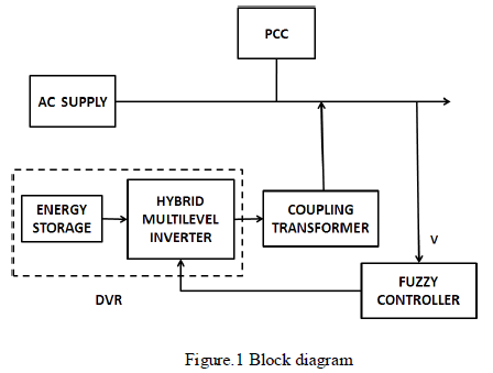 |
| The necessary amount of energy that must be delivered by the energy source depends on load MVA requirement, control strategy applied, deepest sag to be protected. Under normal conditions, the short circuit impedance of the injection transformer determines the voltage drop across the DVR. This impedance must be low and has an impact on the fault current through the VSI on secondary side caused by a short-circuit at load side. The filter design is also affected by the impedance of the injection transformer. In case of fault or over current exceeding the rating of DVR on the load side, solid-state bypass switches or electromechanical bypass switches must be added as a measure to protect DVR from getting damaged. [4] |
MULTI LEVEL INVERTER |
| The most popular topologies of multilevel converters are the neutral- point-clamped inverter (NPC), the flying capacitor inverter (FC), and the cascaded Hbridge (CHB) inverter. Each one of these inverters has its own merits and demerits. In the NPC inverter, multiple dc sources are generated by splitting a single-dc bus voltage using capacitor banks. This configuration has large number of clamping diodes and presents the problem of dc bus capacitor unbalance especially with high number of voltage levels. An interesting work for balancing capacitors in NPC inverter that can be operated in limited modulation range. A pulse-width modulation (PWM) control scheme to balance the dc link capacitor voltages of the NPC inverter, connected in cascade with a twolevel inverter. |
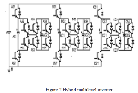 |
| The proposed topology [1] shown in figure 2 has a three-level FC inverter with dc bus voltage of vdc and fc voltage equal to Vdc /2, which can generate voltages of 0, vdc /2, and vdc with respect to point 0. A capacitor-fed hbridge is cascaded to each Phase of the inverter. The voltage across the h-bridge capacitor has to be maintained at vdc /4. This combination can produce Voltage levels of 0, vdc /4, vdc /2, 3vdc /4, vdc , −vdc /4, and 5vdc /4. Out of these, the voltages −vdc /4 and 5vdc /4 are not used in the proposed inverter as they do not have redundant Switching states to balance the capacitor voltages. The capacitor voltages remain unaffected while producing the voltages vdc and 0. The capacitors can either be charged or discharged in any direction of the current for the voltages vdc /4, vdc /2, and 3 vdc /4 as respectively. |
| In each phase, the switches S1, S2, S3, S4 and S1, S2, S3, S4 are operated in complementary manner. The output voltage is based on the switching states that decide the path of the current flow. For voltage levels of vdc /4 and 3 vdc /4, there are three redundant states. By switching between these three states the capacitors C1 and C2 can be charged or discharged for any direction of the current. The voltage level of vdc /2 has two redundant states .By switching between them, C1 can be charged or discharged based on the current direction. When vdc /2 is applied, the C2 is not affected. |
| As the capacitors can be either charged or discharged by switching between the redundant states, based on the current direction, quick capacitor voltage balancing is possible, irrespective of the load power factor. To maintain the capacitor voltages at fixed value, the capacitor voltages are sampled at regular intervals and a controller is used to switch between the redundant states based on the current direction to balance the capacitor voltages. |
CONTROL SYSTEM |
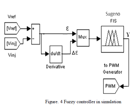
| The aim of the control system is to maintain voltage magnitude at the point where a sensitive load is connected, under system disturbances. The harmonics is generated in the load terminals using six pulse converters with fixed firing angle are connected to the main drive non linear load which is parallel to the sensitive load [3]. Voltage sag is created at load terminals via a three phase fault. The above voltage problems are sensed separately and passed through the sequence analyzer. The control system of the general configuration typically consists of a voltage correction method which determines the reference voltage that should be injected by DVR and the VSI control which is in this work consists of PWM with Fuzzy controller [4]. The controller input is an error signal obtained from the reference voltage and the value of the injected voltage. DVR Control strategies fall mainly in one of the two categories namely linear control methods and Non-linear control methods. Linear control methods can be employed with the feedback, the Feed-foreword and the combined feed controllers. Non-Linear control methods comprising the Artificial Neural Networks (ANN), the Fuzzy Logic (FL) and the Space Vector (SV) controllers Although feedback controllers are popular, they Require load and source tracking, whereas feedforeword controllers are much simpler yet open-looped, there is no Feedback from the load voltage or current. The control of the proposed DVR is based on a fuzzy logic The PWM signal generator that controls the DVR inverter to generate the required injected voltage [9]. |
 |
| Unlike Boolean logic, fuzzy logic allows states (membership values) between 0 or 1. Its major features are the use of linguistic variables rather than numerical variables. Linguistic variables, defined as variables whose values are sentences in a natural language (such as small and big), may |
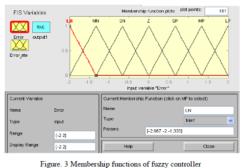 |
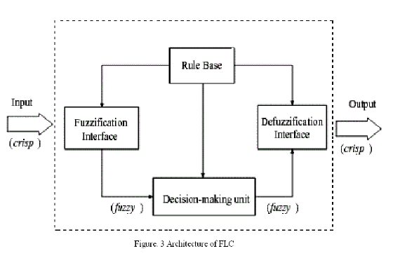
| Be represented by fuzzy sets [6]. The general structure of an FLC is represented in Figure 3 and comprises four principal components, a fuzzification interface which converts input data into suitable linguistic values; a knowledge base which consists of a data base with the necessary linguistic definitions and control rule set; a decision making logic which, simulating a human decision process, infers the fuzzy control action from the knowledge of the control rules and the linguistic variable definitions; and a defuzzification interface which yields a nonfuzzy control action from an inferred fuzzy control action.. The process also same as before except the controller now is Fuzzy Logic. The FL controller consists of three linguistic variables from input which is; Negative (N), Zero (Z) and Positive (P). Each parameter from linguistic variables for error signal for delta error, there are three linguistic variables, Negative (N), Zero (Z) and Positive (P). |
 |
SIMULATION RESULTS AND DISCUSSION |
 |
| Voltage Swell is defined by IEEE 1159 as the increase in the RMS voltage level to 110% - 180% of nominal, at the power frequency for durations of half cycle to one (1) minute. It is classified as a short duration voltage variation phenomena, which is one of the general categories of power quality problems mentioned in the second post of the power quality basics series of this site. Voltage swell is basically the opposite of voltage sag or dip . |
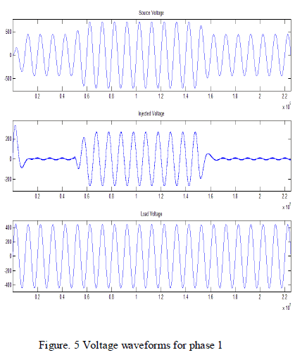
| The above figure 5 shows the voltage waveforms for phase 1 source voltage, injected voltage and load voltage. In the first waveform voltage swell is produced between time periods of 0.6 to 1.5 seconds which is mitigated by injecting voltage by DVR and the amount of injection is controlled by fuzzy logic controller in second waveform and in the third waveform because of injected voltage the load voltage waveform is compensated during the faulted time period and hence the power quality is maintained by mitigating the voltage swells. |
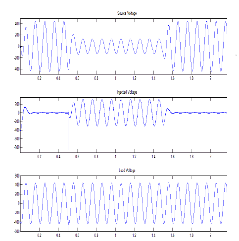 |
| Figure. 6 Voltage waveforms for phase 2 |
| Voltage sag is defined as the reduction of rms voltage to a value between 0.1 and 0.9p.u and lasting for duration between 0.5 cycles to 1 minute. Voltage sags are mostly caused by system faults and last for durations ranging from 3 cycles to 30 cycles depending on the fault clearing time. Starting of large induction motors can result in voltage dip as the motor draws a current up to 10 times the full load current during the starting. |
| The above figure 6 shows the voltage waveforms for phase 2 source voltage, injected voltage and load voltage. In the first waveform voltage sagl is produced between time periods of 0.6 to 1.5 seconds which is mitigated by injecting voltage by DVR and the amount of injection is controlled by fuzzy logic controller in second waveform and in the third waveform because of injected voltage the load voltage waveform is compensated during the faulted time period and hence the power quality is maintained by mitigating the voltage sags |
| The above figure 7 shows the source voltage and load voltage of three phases. In the first waveform the distribution side voltage is produced with voltage sags and swells during the time periods of 0.6 to 1.5 seconds in two phases and in the second waveform by using DVR the dc supply stored in the energy storage system is converter into ac by the multilevel inverter and injected during the faulted voltage into the distribution system by series injection of voltage thereby the load voltage is compensated and hence the power quality is maintained at the consumer end. |
CONCLUSION |
| Nowadays, reliability and quality of electric power is one of the most discuss topics in power industry, there are numerous types of power quality issues and power problems Among them, two power quality problems have been identified to be of major concern to the customers are voltage sags and voltage swells .In this paper Dynamic Voltage Restorer (DVR) is used to overcome the voltage sag and swell with the use of hybrid multilevel inverter is presented to improve the Power Quality. This is proved by MATLAB simulation results. The result indicates that the load voltage is improved within few seconds using DVR when faults occur in distribution system which shows the DVR’s excellent performance and the control system in order to protect sensitive equipment from PQ disturbances. |
References |
|