Keywords
|
| Active filter, Unbalanced load, power quality. |
INTRODUCTION
|
| Many social and economic activities depend on electrical energy quality and efficiency. Both industrial and commercial users are interested in guaranteeing the electrical waveform quality, which supplies their different systems. The nonlinear load can generate current harmonics and/or voltage harmonics, which makes worse the power quality. Therefore, these harmonics must be mitigating. In order to achieve this, series or parallel configurations or combinations of active and passive filters have been proposed depending on the application type [1], [2]. |
| Since the beginning of the 1980s, active power filters(APFs) have become one of the most habitual compensation methods. A usual APF consists of a three-phase pulse width modulation (PWM) voltage source inverter. The APF can be connected either in parallel or in series with the load. The first one is especially appropriate for the mitigation of harmonics of the loads called harmonic current source. In contrast, the series configurations is suitable for the compensation of loads called harmonic voltage source. The shunt connection APF is the most studied topology [6]– [10]. However, the costs of shunt active filters are relatively high for large-scale system and are difficult to use in highvoltage grids. In addition, their compensating performance is better in the harmonic current source load type than in the harmonic voltage source load type [10]. Another solution for the harmonic problem is to adopt a hybrid APF. The hybrid topologies aim is to enhance the passive filter performance and power-rating reduction of the active filter. Two configurations have been mainly proposed: active filter connected in series with a shunt passive filter and series active filter combined with shunt passive filter. Both topologies are useful to compensate harmonic current source load type. However, when the load also generates voltage harmonics, the second topology is the most appropriate. |
| This paper proposes a control strategy of shunt hybrid active filter for reactive power compensation considering unbalanced load. The hybrid active filter, being composed of a harmonic frequency-tuned LC filter and an active filter, is connected in parallel at the point of the common coupling (PCC). In the proposed method, the definition of the negative-sequence power [7] is applied to estimate the reactive power induced by the unbalanced load, while improve the accuracy of the conventional real and reactive power estimation. The hybrid active filter is designed to dynamically compensate the corresponding reactive power and harmonic current in case of load varying. |
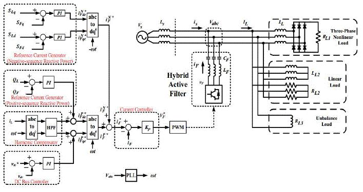
| Fig.1. shows the simplified circuit diagram of the hybrid active filter in industrial system and the proposed control block diagram. An unbalanced load, inductive loads and a diode rectifier are considered. The hybrid active filter is installed in parallel at the PCC, and the hybrid filter is composed of a LC passive filter and a voltage source inverter in series connection. The LC filter functions capacitive and draws amount of leading current at system frequency, then the active filter in series modifies this output reactive power according to the load condition. The control block diagram mainly includes reference current generator for positive- and negative-sequence reactive power compensation, harmonic compensator and a dc bus controller, while a modified instantaneous power calculation provides the load and filter reactive power for the reference current generator. Finally, the obtained reference filter current synthesizes the switching signals through the current control and the PWM. The following section deals with the composition of reference filter current and overall control algorithm. |
OPERATION PRINCIPLE OF THE PROPOSED SHUNT HYBRID APF TOPOLOGY`
|
| The operation principle of the proposed shunt hybrid APF topology is illustrated in Fig. 1 Fig -1: Operation Principle of the Basic Shunt Hybrid Power Filter, The operation principle of the proposed shunt hybrid APF topology is illustrated in Fig. 1. It consists of a shunt active filter and tuned passive filters (TPFs) connected in parallel with the nonlinear load which is connected to ac source. The two TPFs are designed to absorb 5th and 7th harmonic currents with the principle of series resonance and SAF compensates remaining harmonics. The SAF generates compensation current (if) equal to harmonic load current (Ila). |
| Definition of Negative-Sequence Power |
| This section introduces the four components of the fundamental power. They are active and reactive positive-sequence components P and Q and the two components of the negative-sequence power SD and SQ. |
| The three-phase balanced voltages Vabc and the unbalanced Currents iabc are considered in the three-phase system, where the unbalanced currents including positive- and negative-sequence components. |
| These instantaneous phasevoltages and the currents are converted into ∝-β coordinates by applying Clark Transformation. Then the four electrical quantities [p, q, sd, sq] are defined as: |
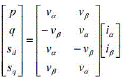 |
| Where the v∝, vβ, i∝ and iβ are the instantaneous phase voltages and the current in ∝-β coordinates. The arguments p and q are the instantaneous real and imaginary powers defined by Akagi et al. [11], while the arguments sd and sq are defined as the negative-sequence powers. These negative-sequence powers are generated by the “assumed” negativesequence voltage [v∝, -vβ] and the “actual” current [i∝, iβ]. |
| The relationship between [p, q] and [sd, sq] becomes more clear by considering the instantaneous power vectors F and B on the complex plane defined by the following expressions: |
 (2) (2) |
 (3) (3) |
| Where SF and SB present the amplitude of the positive and negative-sequence apparent power, and θp, θn are their phase angles. It is clear that |
 (4) (4) |
| This means that the first term of B in (3), which are dc components, equals to the second term of F in (2) by applying a coordinate transformation . |
| B. Power Detection |
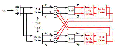
| Fig. 2 shows the block diagram for detecting P, Q, SD and SQ. It can be realized simply by adding LPFs (low pass filters) and/or band-reject-filters to filter the ac components, especially 2ω components in (2) (3). However, the filters with both a small tracking time and a significant attenuating characteristic are difficult to be realized. |
| According to (4), when P and Q are applied the coordinate transformation ejzwt, the results will equal to the 2ω components of sd and sq in (3). Based on this characteristic, the proposed block diagram in Fig. 2 feedbacks the estimated P, Q, SD and SQ with coordinate transformations to eliminate the 2ω components in [p, q, sd , sq ], before the LPFs are applied. For instance, P and Q eliminate the 2ω components of sd and sq, while SD and SQ reduce the 2ω components of p and q. |
| This feedback topology improves the 2ω frequency attenuating characteristic of the entire power detecting diagram. |
| C. Reference Current Generator |
| Due to series capacitor C, the LC filter draws amount of leading current at system frequency. When the inverter outputs a fundamental voltage being in phase with the fundamental leading current of the passive filter, the active power contributed by the leading current and fundamental output voltage will be delivered into the dc side. Analogously, when the inverter output voltage is orthogonal to the fundamental leading current of the passive filter, the filter reactive power will be varied. Therefore, the quantity to be provided by the positive-sequence reactive power QF feedback loop will be in positive-sequence synchronous reference frame (SRF) with the system angle +ωt, where the d-axis in SRF implies the components in phase with the grid voltage and the q-axis implies the components orthogonal to the grid voltage. A phase-locked loop (PLL) is required for grid synchronization. The definition of the PI regulator is shown as: |
 |
| Where s is the Laplace operator, kp and ki are proportional and integral gains, respectively. Similarly, the difference between the load negative-sequence power SLd and the filter negative-sequence power SFd in d coordinate determines the fundamental current commands by applying the PI regulator in negative-sequence SRF, while the error between SLq and SFq determines the . |
| D. Harmonic Compensator |
| The harmonic load current can be determined by using the SRF transformation as shown in Fig.3. In the SRF, the fundamental component becomes a dc value, whereas the harmonic components are ac value. Therefore, the harmonic load current iLde,h, iLqe,h in the SRF can be simply extracted by high-pass filters (HPFs). Then the harmonic load current is treated as the harmonic reference filter current iFde,h, iFqe,h in the positive-sequence SRF. |
| E. DC Bus Control |
| Because the series capacitor draws the fundamental reactive current from the grid, the active filter can draw real power by outputs a fundamental voltage in phase with the leading current. According to this feature, the dc voltage of the hybrid active filter can be regulated by a PI controller to adjust the fundamental reactive filter current according to the dc bus voltage and the reference dc voltage vdc*. |
| F. Current Control |
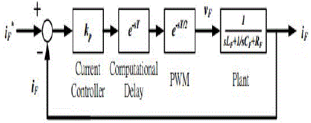
| After transferring the positive- and negative-sequence reference filter current into the three-phase system, the sum of the three-phase reference filter current iF,abc applies a proportional controller and the space vector PWM to synthesize the gating signals of the active filter. Therefore, the proposed hybrid active filter can be controlled with the desired compensating current. |
PROPORTIONAL INTEGRAL CONTROLLER
|
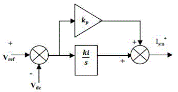
| PI controller algorithm involves two separate parameters; the Proportional and the Integral. The Proportional value determines the reaction to the current error; the Integral determines the reaction based on the sum of recent errors. A comparison of the average and the reference values of the dc bus voltage for the shunt AF results in a voltage error, which is fed to a proportional integral (PI) controller and the output of the PI controller is multiplied by the mains voltage waveform Vsa, Vsb, Vsc in order to obtain the supply reference currents ,Isa*,Isb*,Isc* |
| A PI controller used to control the DC-bus voltage is shown in Figure 4 whose transfer function can be represented as |
 |
| Where, kp is the proportional constant that determines the dynamic response of the DC-bus voltage control, and ki is the integration constant that determines it’s settling time. |
| It can be noted that if kp and ki are large, the DC-bus voltage regulation is dominant, and the steady-state DC-bus voltage error is low. On the hand, if kp and ki are small, the real power unbalance gives little effect to the transient performance. Therefore, the proper selection of kp and ki is essentially important to satisfy above mentioned two control performances. The computed three-phase supply reference currents are compared with the sensed supply currents and are given to a hysteresis current controller to generate the switching signals to the switches of the shunt AF which makes the supply currents follows its reference values. |
MATLAB MODELING AND SIMULATION RESULTS
|
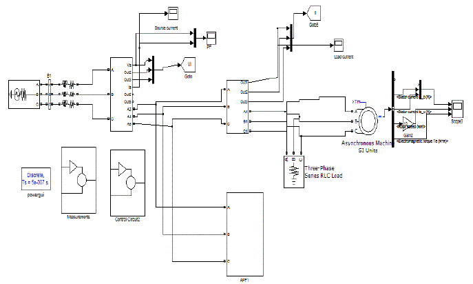
| Simulation circuit is established to verify the proposed strategies, where only nonlinear loads, inductive loads and unbalanced loads are considered. The inverter of the hybrid active filter is composed of IGBTs and a dc capacitor. Here simulation results are carried out in different cases 1). Implementation of Proposed Hybrid Active power Filter. 2). Implementation of Proposed Hybrid Active power Filter Applied to Induction Machine. |
| Case 1: Implementation of Proposed Hybrid Active power Filter. |
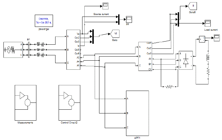
| Fig.5 shows the Matlab/Simulink Model of proposed Hybrid Active Power Filter using Matlab/Simulink Platform. |
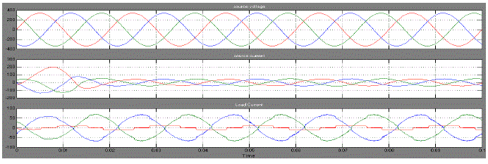
| Fig.6 shows the Source Voltage, Source Current, and Load Current of proposed Hybrid Active Power Filter. |
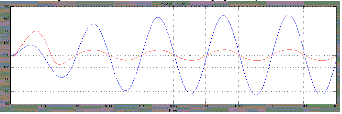
| Fig.7 shows the Power Factor of Proposed Hybrid Active Power Filter. |
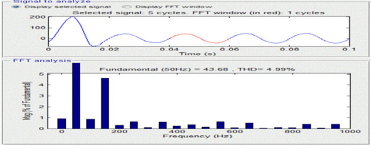
| Fig.8 shows the FFT Analysis of Phase A Source Current of Proposed Hybrid Active Power Filter,we get THD is 4.99%.The THD is the most common indicator to determine the quality of ACwaveforms. Using the Fast Fourier Transform (FFT), the harmonic spectrum of the source current under different compensation conditions is presented. Then, the THD comparison is carried out for the simulation results and from the spectra plot, it can be seen that the source current contains large amount of harmonic current components (5th & 7th components are higher magnitude i.e 11 and 7 respectively as shown in fig 8) of frequencies below 1 kHz and the THD is 4.99% (According to IEEE-519 standards the THD limits on the magnitude of harmonic current frequencies should be within 5% [1][2]). |
| Case 2: Implementation of Proposed Hybrid Active power Filter Applied to Induction Machine Drive. |
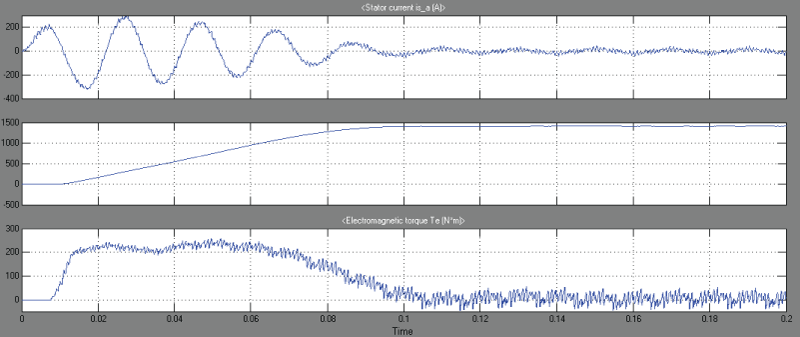
| Fig.10 shows the Stator Current, Speed, and Electromagnetic Torque of proposed Hybrid Active Power Filter Applied to Induction Machine Drive. |
CONCLUSION
|
| The instantaneous real-power theory generates the reference currents required to compensate the distorted line current harmonics and reactive power. It also tries to maintain the dc-bus voltage across the capacitor constant by using the different controllers. A control strategy of shunt hybrid active filter is proposed for reactive power compensation considering unbalanced load, here load is considered as induction machine for find out the performance characteristics of the machine. The instantaneous power theory with negative-sequence power definition are employed to generate the reference filter current to compensate the power system, and the hybrid active filter can dynamically compensate the corresponding reactive power in case of load varying. The proposed instantaneous real-power controller uses reduced computation for reference current calculations compared to conventional approach. Therefore, the power system will behave as a balanced resistive network even in unbalanced and nonlinear loadings as well as machine loadings. |
Figures at a glance
|
 |
 |
 |
 |
 |
| Figure 1 |
Figure 2 |
Figure 3 |
Figure 4 |
Figure 5 |
 |
 |
 |
 |
 |
| Figure 6 |
Figure 7 |
Figure 8 |
Figure 9 |
Figure 10 |
|
References
|
- R. L. Almonte and A. W. Ashley, “Harmonics at utility industrial interface: a real world example,” IEEE Trans. Ind. Appl., vol. 31, no. 6, pp.1419–1426, Nov./Dec. 1995.
- R. H. Simpson, “Misapplication of power capacitors in distribution systems with nonlinear loads–three case histories,” IEEE Trans. Ind. Appl.,vol. 41, no. 1, pp. 134–143, Jan. 2005.
- H. Akagi, S. Srianthumrong, and Y. Tamai, “Comparison in circuit configuration and filtering performance between hybrid and pure shuntactive filters,” in IEEE Industry Applications Conference 38th IAS Annual Meeting, 2003, pp. 1195–1202.
- S. Srianthumrong and H. Akagi, “A medium-voltage transformerless ac/dc power conversion system consisting of a diode rectifier and a shunthybrid filter,” IEEE Trans. Ind. Appl., vol. 39, no. 3, May/Jun. 2003, pp. 874–882.
- T.-L. Lee, Z.-J. Chen and S.-H. Hu, “Design of a power flow control method for hybrid active front-end converters,” in IEEE Power Electronicsand Drive Systems (PEDS), 2009.
- G.Satyanarayana., K.N.V Prasad, G.Ranjith Kumar, K. Lakshmi Ganesh, "Improvement of power quality by using hybrid fuzzy controlled basedIPQC at various load conditions," Energy Efficient Technologies for Sustainability (ICEETS), 2013 International Conference on , vol., no.,pp.1243,1250, 10-12 April 2013.
- Matsui, M.; Fukao, T. "A detecting method for active-reactive-negative-sequence powers and its application," IEEE Trans. on Ind. Appl., vol. 26,no. 1, 1990 , pp. 99–106
- G. SatyaNarayana, Ch. Narendra Kumar, Ch. Rambabu “ A Comparative Analysis of PI Controller and Fuzzy Logic Controller for HybridActive Power Filter Using Dual Instantaneous Power Theory” International Journal of Engineering Research & Development, Vol-4, Issue-6, p.p.29-39, Oct, 2012.
- K. Lee, T. M. Jahns, W. E. Berkopec and T. A. Lipo, “Closed-form analysis of adjustable-speed drive performance under input-voltageunbalance and sag conditions,” IEEE Trans. on Ind. Appl., vol. 42, \ May/Jun. 2006, pp. 733–741.
- IEEE Recommended Practice for Electric Power Distribution for Industrial Plants, IEEE Std. 141-1993.
- H.Akagi, “Active Harmonic Filters,” Proceedings of the IEEE, vol. 93, no. 12, pp. 2128–2141, Dec. 2005.
|