Keywords
|
| Synchronous Reference Frame, instantaneous current component theory, Modified SRF, Active Filter, Harmonics. BLDC Drive. |
INTRODUCTION
|
| Voltage instability problems are attracting more and more attention in the areas of power system operation, planning, and control. These problems are becoming a more serious concern with the ever-increasing utilization and higher loading of existing transmission systems, particularly with increasing energy demands, and competitive generation and supply requirements. Under the heavy load conditions, a significant voltage drop may occur in the system. Voltage sags can occur at any instant of time, with amplitudes ranging from 10 – 90% and a duration lasting for half a cycle to one minute [1]. Voltage swells are not as important as voltage sags because they are less common in distribution systems. Voltage dips are one of the most occurring power quality problems. Off course, for an industry an outage is worse, than a voltage dip, but voltage dips occur more often and cause severe problems and economical losses. Utilities often focus on disturbances from end-user equipment as the main power quality problems. This is correct for many disturbances, flicker, harmonics, etc., but voltage dips mainly have their origin in the higher voltage levels. Faults due to lightning, is one of the most common causes to voltage dips on overhead lines. |
| If the economic losses due to voltage dips are significant, mitigation actions can be profitable for the customer and even in some cases for the utility. Since there is no standard solution which will work for every site, each mitigation action must be carefully planned and evaluated. There are different ways to mitigate voltage dips, swell and interruptions in transmission and distribution systems. At present, a wide range of very flexible controllers, which capitalize on newly available power electronics components, are emerging for custom power applications [3, 4].Amongthese, the distribution static compensator and the dynamic voltage restorer are most effective devices, both of them based on the VSC principle. |
| With the advancement of power electronics and emergence of new multilevel converter topologies, it is possible to work at voltage levels beyond the classic semiconductor limits. The multilevel converters achieve high-voltage switching by means of a series of voltage steps, each of which lies within the ratings of the individual power devices. Among the multilevel Converters [1-4], the cascaded H-bridge topology (CHB) is particularly attractive in high voltage applications, because it requires the least number of components to synthesize the same number of voltage levels. Additionally, due to its modular structure, the hardware implementation is rather simple and the maintenance operation is easier than alternative multilevel converters. The multilevel voltage source inverter is recently applied in many industrial applications such as ac power supplies, static VAR compensators, drive systems, etc. One of the significant advantages of multilevel configuration is the harmonic reduction in the output waveform without increasing switching frequency or decreasing the inverter power output [5-11]. The output voltage waveform of a multilevel inverter is composed of the number of levels of voltages, typically obtained from capacitor voltage sources. The so-called multilevel starts from three levels. As the number of levels reach infinity, the output THD approaches zero. The number of the achievable voltage levels, however, is limited by voltage unbalance problems voltage clamping requirement, circuit layout, and packaging constraints. |
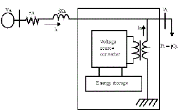
| A STATCOM, which is schematically depicted in Fig.1, consists of a three-level VSC, a dc energy storage device, a coupling transformer connected in shunt to the DS. The VSC converts the dc voltage across the storage device into a set of three-phase ac output voltages. These voltages are in phase and coupled with the ac system through the reactance of the coupling transformer. Suitable adjustment of the phase and magnitude of the STATCOM output voltages allows effective control of active and reactive power exchanges between the STATCOM and the ac system. Such configuration allows the device to absorb or generate controllable active and reactive power. |
| Here, such device is employed to provide continuous Voltage regulation using an indirectly controlled converter. As shown in Figure-1 the shunt injected current Ish corrects the voltage sag by adjusting the voltage drop across the system impedance Zth. The value of Ish can be controlled by adjusting the output voltage of the converter. The shunt injected current Ish can be written as, |
 (1) (1) |
 (2) (2) |
CURRENT CONTROL MODE
|
| A new approach has been proposed to control current with Peak Current mode control (PCM) without any instability. PCM is instable for duty cycles more than half. This approach adopts PCM for duty ratios smaller than half, but it changes the control strategy for duty ratios larger than half. In traditional PCM method, the circuit current is controlled in such a way that it does not become larger than the reference. When the current in each cycle crosses the reference, the control method will change the switch status to decrease current. However, this algorithm will cause instability to the current for duty ratios greater than half. The new method will control circuit current in duty ratios larger than half in such a way that it does not become smaller than the reference. Therefore, as the current in each cycle crosses the reference, the control method will change the switch status to increase the current. So depending on the duty cycle status whether it is greater or lower than half, the controller will switch to the proposed method or the traditional PCM, respectively. This will avoid the instabilities for all duty cycles [6]. |
APPLICATION OF THE PROPOSED CURRENT METHOD ON THE STATCOM
|
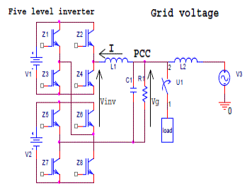
| The general schematic o the project is shown in Fig. 2. The output voltage of the inverter used as a single phase STATCOM shall be in phase with the grid voltage. At the same time, the duty cycle shall be controlled according to the new current control approach. In order to adopt this approach, the duty cycles shall be identified whether it is greater or smaller than half. In order to define the duty cycle for different voltage conditions, the inductor current should be calculated according to the inductor voltage drop. If the inductor voltage drop during current increase in a switching period is larger than the one for current decrease instance, the duty cycle will be less than half. It is because it takes less time for the current to rise to its final value than the time for it to decrease to its bottom value. This is well shown in voltage current equation of inductor as in (1) and (2). |
 (3) (3) |
 (4) (4) |
| According to Equation (2) the different voltage conditions and its related duty cycle is calculated and shown in Table I. For example if the grid voltage is below half unit of the DC voltage supply, the voltage that is generated in the output of the converter is zero or one unit of the DC voltage. In order to increase the current, zero will be assigned to the output of the converter. On the other hand, to decrease STATCOM current one unit of the DC voltage supply will be assigned to output of the converter. In this case the inductor voltage drop when current increasing is equal to the grid voltage and the inductor voltage drop when current decreasing is the difference between grid voltage and one DC voltage supply. Since it was assumed that the grid voltage is lower than half of the DC voltage supply, the inductor voltage drop during current increase is lower than the voltage drop during current decrease. This means that it takes a longer time for the current to increase than for it to decrease as in Fig. 4 which leads to the duty cycle larger than half as in Table I. |
| Since the output voltage of the converter shall be in phase with the grid voltage. This is a criterion to change the switch states during voltage zero crossings. However, the main measure for changing switch states is to follow the reference current according to the mentioned control method. It means that according to the duty cycle states that can be defined by Equation (2) the inverter current is controlled. The duty cycle status for different grid voltage amplitudes is mentioned in Table I. In this table, if the absolute voltage amplitude is in certain ranges against DC voltage supplies, the duty ratio status is defined for the controller. |
| In order to manipulate the control method on the multilevel inverter, the conditions that affect the circuit current should also be identified. There should be a table to define the true voltage that should be imposed to the inverter output voltage terminals. There are some measures to select the appropriate output voltage. One of the criteria is that the grid voltage should be always between the nearest available DC-voltage magnitude that can be generated by the inverter as shown in Table II. For example, if the grid voltage amplitude is greater than VDC and lower than 2 VDC, converter the output voltage will switch between VDC and 2 VDCand lower than 2 VDC, converter the output voltage will switch between VDC and 2 VDC. |
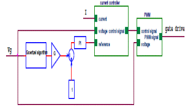
| Table II will be used to implement the controller utilizing a DSP. According to the tables above and measuring the instantaneous current and voltage, the DSP decides the status of switches. The block diagram of the controller in DSP according to the tables above is in Fig. 3 According to Fig. 3, the grid voltage (Vg) and inverter current (I) are measured and fed into the DSP. The DSP controls the switches according to the network parameters and tables mentioned above. The current controller block in Fig. 3 generates the reference current by multiplying the PI output value with the sinusoidal signal which is 90 degree leading the grid voltage. This signal is considered as the reference in the current controller block. |
| The controller will then manipulate the interfacing current (I) according to the network conditions and the tables above. The control signal will then be fed into the PWM block to activate and on the selected switches. True set of switches are selected according to Table I and Table II. Simulation results of the proposed method are depicted in Fig. 4 and Fig. 5. In Fig. 4 the inverter current (I) in capacitive operation (inverter current leading grid voltage by 90 degree phase) and reference current, which is controlled according to the proposed criteria, is depicted. In this figure the inverter current is controlled according to duty cycle (D) conditions in a complete sinusoidal cycle The duty cycle (D) conditions (smaller or greater than half) are also mentioned in the figure. |
MATLAB/SIMULINK MODELLING AND SIMULATION RESULTS
|
| Here simulation is carried out in two topologies, three level STATCOM, 5-level multilevel converter STATCOM compensating the voltage sags & swells for improvement of power quality |
| A. Without Compensator |
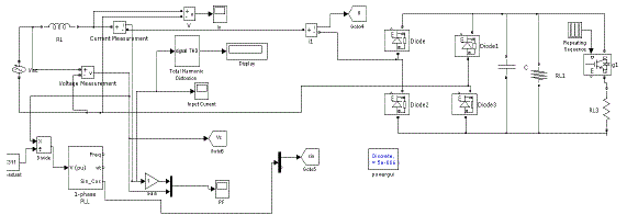
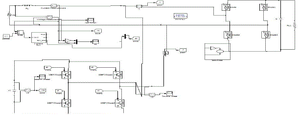
| Fig. 4 shows the MATLAB/Simulink model of Single Phase Circuit without STATCOM. The corresponding results are shown in Fig .5 and Fig .6. |
| Fig. 5 shows the output waveforms showing the sag content in it. This represents the sag voltage in the condition without STATCOM. |
| Fig. 6 shows the output waveforms of the power factor. It is clear that there is no unity power factor because STATCOM is not used. |
| B. With 3-Level Inverter Based STATCOM |
| Fig .7 shows the Simulink Circuit of Single phase circuit with 3-level STATCOM |
| Fig.8 shows the grid current when 3 level inverter is connected to single phase circuit. |
| Fig.9 shows the output waveforms of the unity power factor. It is clear that voltage and current are in phase and there is unity power factor because 3level based STATCOM is used. |
| Fig .10 shows the 3 level output voltage of proposed level STATCOM. |
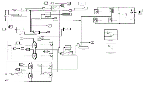
| Fig .11 shows the Simulink Circuit of Single phase circuit with 5-level multilevel STATCOM |
| Fig 12 shows the output waveforms of the STATCOM current during sag condition. |
| Fig .13 shows the Grid voltage of the STATCOM circuit. |
| Fig 14 shows the output waveforms of the unity power factor. It is clear that voltage and current are in phase and there is unity power factor because STATCOM is used. |
CONCLUSIONS
|
| A new 3 Level & 5-Level Based Multilevel STATCOM controller on Goertzel sag detection and a new current control mode is proposed and simulated. The sag detection method is suitable for DSP implementation. It does not require extensive calculations such as in FFT nor is it prone to noise interference. The proposed current control method has also great superiority over conventional voltage control methods in terms of simplicity and harmonic spectrum. It is a fixed frequency approach and does not have the filtering and EMI problems as in the hysteresis method. The control method is also applied on a cascade multilevel inverter to make a multilevel STATCOM. Both the controllers are in single phase controller and can handle all single phase voltage sag disturbances. The simulations show that 3level & 5level STATCOM can effectively work to mitigate voltage sag and maintain voltage in safe limits. |
Tables at a glance
|
 |
 |
| Table 1 |
Table 2 |
|
Figures at a glance
|
 |
 |
 |
 |
 |
| Figure 1 |
Figure 2 |
Figure 3 |
Figure 4 |
Figure 5 |
 |
 |
 |
 |
 |
| Figure 6 |
Figure 7 |
Figure 8 |
Figure 9 |
Figure 10 |
 |
 |
 |
 |
| Figure 11 |
Figure 12 |
Figure 13 |
Figure 14 |
|
References
|
- Naidoo. R, Pillay. P, “A New Method of Voltage Sag and Swell Detection” , IEEE Transactions on Power Delivery ,Volume 22, Issue 2,Page(s):1056 – 1063, April 2007.
- Giroux. P, Sybille. G, Le-Huy.H., “Modeling and simulation of a distribution STATCOM using Simulink's Power System Blockset”, The 27thAnnual Conference of the IEEE Industrial Electronics Society, 2001. IECON '01.Volume 2, Page(s):990 – 994, Dec - 2001.
- Rulphchasseing, “Digital signal processing and applications with the C6713 and C6416 DSK” , john wiley& sons publications,(2005).
- E. Najafi and A. H. M. Yatim, "A novel current mode controller for a static compensator utilizing Goertzel algorithm to mitigate voltage sags "Energy Conversion and Management, vol. 52 pp. 1999-2008, 2011.
- 5. Najafi, E.; Yatim, A.H.M; , "A D-STATCOM based on Goertzel algorithm for sag detection and a novel current mode controller," IndustrialElectronics and Applications (ICIEA), 2010 the 5th IEEE Conference on , vol., no., pp.1006-1011, 15-17 June 2010
- Ben-Sheng Chen; Yuan-Yih Hsu; , "A Minimal Harmonic Controller for a STATCOM," IEEE Transactions on Industrial Electronics, vol.55,no.2, pp.655-664, Feb. 2008
- An Luo; Ci Tang; ZhikangShuai; Jie Tang; Xian Yong Xu; Dong Chen; , "Fuzzy-PI-Based Direct-Output-Voltage Control Strategy for theSTATCOM Used in Utility Distribution Systems," IEEE Transactions on Industrial Electronics, , vol.56, no.7, pp.2401- 2411, July 2009
- Chien-Hung Liu; Yuan-Yih Hsu; , "Design of a Self-Tuning PI Controller for a STATCOM Using Particle Swarm Optimization," IEEETransactions on Industrial Electronics, vol.57, no.2, pp.702- 715, Feb. 2010
|