Keywords
|
| GSM, LabVIEW, pH, CO, Temperature. |
I. INTRODUCTION
|
| The terms monitoring and assessment are frequently confused and used synonymously. The process of industrial quality assessment is an evaluation of the industrial quality in relation to standard quality set by pollution control board. Particular attention is given to factors which may affect human health and the health of the natural system itself. Environmental quality assessment includes the use of monitoring to define the condition of the water, to provide the basis for detecting trends and to provide the information enabling the establishment of cause effective relationships. |
| Industrial quality monitoring is the collection of information at set locations of different industries and at regular intervals in order to provide the data which may be used to define current conditions, establish trends etc. Due to the complexity of factors determining industrial quality, large variations are found between different industries. Similarly, the response to industrial impacts is also highly variable. |
| The main reason for the assessment of the quality of the industrial environment has been, traditionally, the need to verify whether the observed industrial quality is suitable for intended uses. The use of monitoring has also evolved to determine trends in the quality of the water, air and soil environment and how they are affected by the release of contaminants, other anthropogenic activities, and/or by waste treatment operation (impact monitoring). More recently, monitoring has been undertaken to estimate nutrient or pollutant fluxes discharged to rivers, ground waters, lakes, oceans and soil or across international the boundaries. The assessment of background quality of the industrial environment is also now widely undertaken as it provides a means of comparison with impact monitoring. It is also used simply to check whether any unexpected change is occurring in otherwise pristine pollutants. However, it should be noted that industrial environmental quality is very variable depending on local conditions. |
| Fresh water is a finite resource essential for use in agriculture, industry, propagation of wildlife & fisheries and for human existence. India is a riverine country. It has 14 major rivers, 44 medium rivers and 55 minor rivers besides numerous lakes, ponds and wells which are used as primary source of drinking water even without treatment. Most of the |
| rivers being fed by monsoon rains, which are limited to only three months of the year, run dry throughout the rest of the year often carrying wastewater discharges from industries or cities or towns endangering the quality of our scarce water resources. Similarly working environment in an industry is important for safety of its workers and people who live near to it. Hence it is important to monitor amount of temperature and carbon monoxide level in an industry. |
| The main problem faced in previous papers where either the process was complex or it required high cost for implementation. Also other processes mainly lacked access at remote locations and hence this system proves to overcome these major drawbacks. |
| The main objectives of Industrial pollution monitoring system using LabVIEW and GSM are |
| 1. To determine the quality of effluent management and working environment in industries. |
| 2. To determine the key descriptors to be considered in pollution monitoring. |
| 3. To determine the feasibility and cost of a monitoring program. |
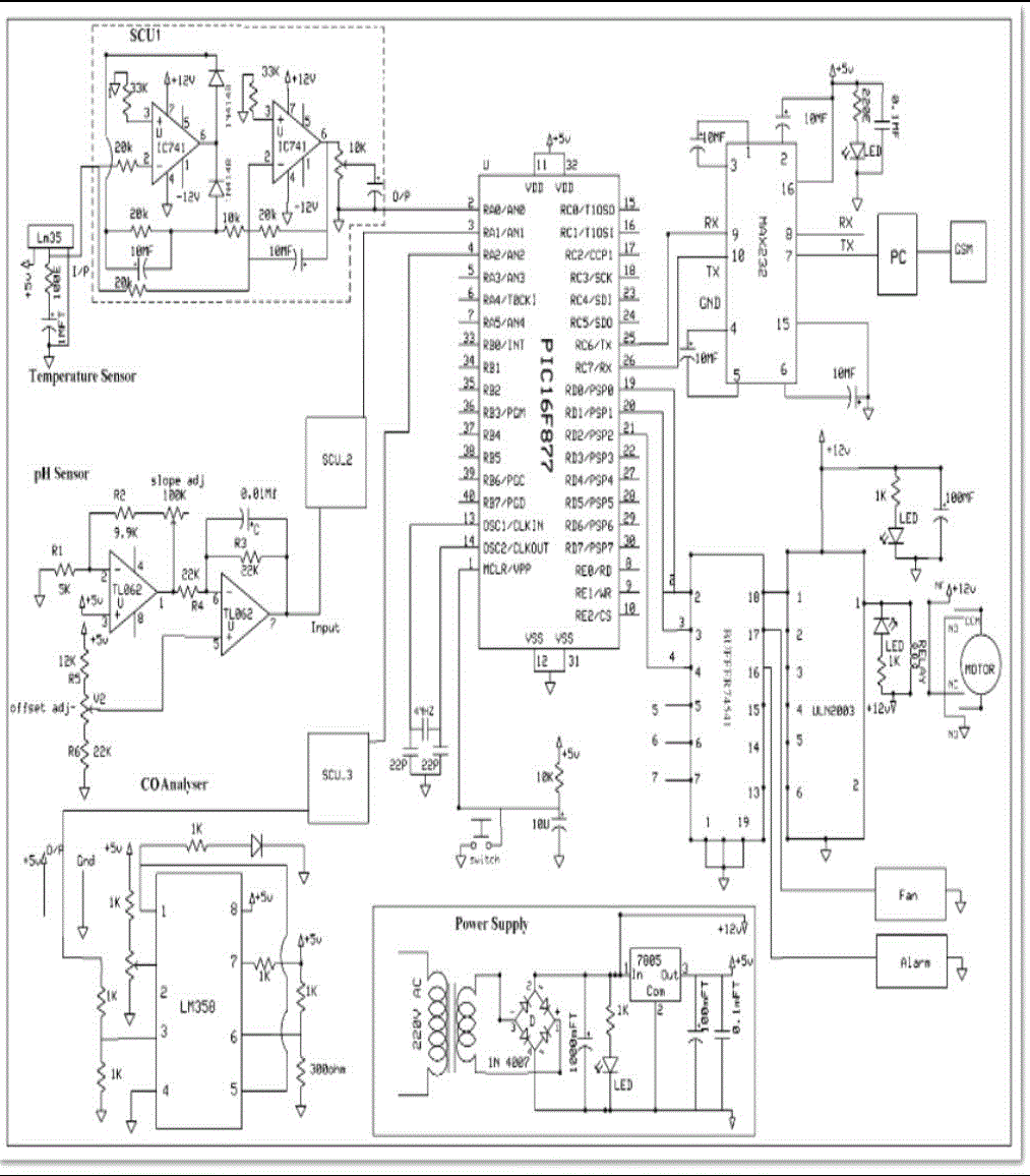
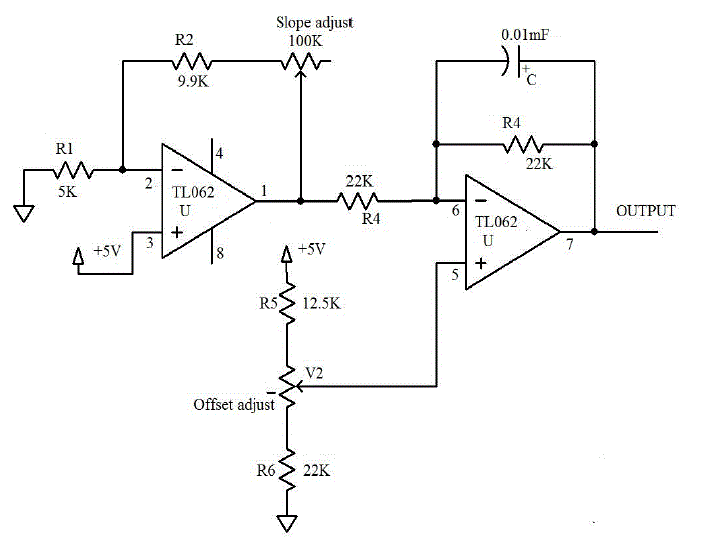
| The above circuit is used to measure the pH of the sample water used and to convert it into voltage signals. The signals from the pH electrode has a typical value of resistance varying from10 MΩ to 100 MΩ and the voltage signals are in range of 0.56 mV. So we have to use IC’s which performs under a low current. |
| Here resistors are used for various current limiting and amplification purposes. Capacitors are also used. In pH mode the reference can be adjusted from pH 0 to pH 12. With the reference properly adjusted, the output in volts will be the actual pH of the indicator solution. Our pH sensor is digitized and is able to communicate with computer and can automatically record data for extended period of time and so on. |
B) TEMPERATURE ANALYSER
|
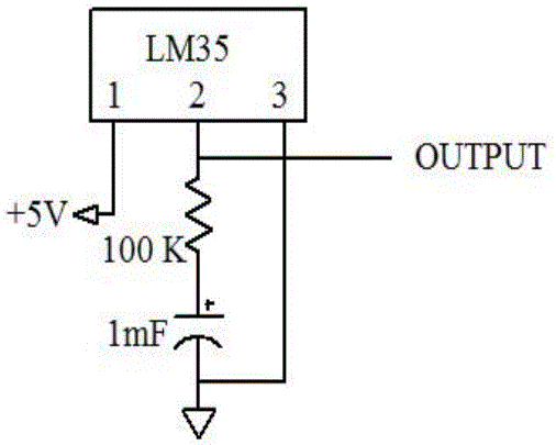
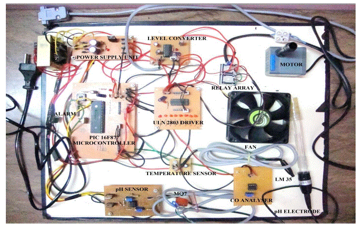
| This gives brief description about temperature analyser used in this project. The LM35 is an integrated circuit sensor that can be used to measure temperature with an electrical output proportional to the temperature. The LM35 generates a higher output voltage than thermocouples and may not require that the output voltage be amplified. Temperature analyser is shown in figure 3. |
| The circuit consists of an LM35 whose terminals are connected to an input voltage of 5V and a series connection of 100kΩ resistance and 100MF capacitance is connected in order to avoid any voltage drop across the circuit. The series connection is grounded and output is taken from terminal 2. It has an output voltage that is proportional to the Celsius temperature. The scale factor is .01V/oC. The LM35 does not require any external calibration or trimming and maintains an accuracy of +/-0.4 oC at room temperature and +/- 0.8 oC over a range of 0 oC to +100 oC. Another important characteristic of the LM35DZ is that it draws only 60 micro amps from its supply and possesses a low self-heating capability. The sensor self-heating causes less than 0.1 oC temperature rise in still air. The LM35 thus has an advantage over linear temperature sensors calibrated in ° Kelvin, as the user is not required to subtract a large constant voltage from its output to obtain convenient Centigrade scaling. |
| C) CO ANALYSER |
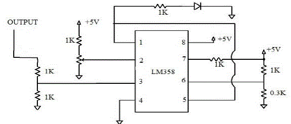
| A carbon monoxide analyser or CO analyser is a device that detects the presence of the carbon monoxide gas in order to prevent carbon monoxide poisoning. The circuit setup consists of analyser head connected to an amplifying unit. A number of supporting resistances are used to avoid voltage drop across the circuit. Resistance value of MQ-7 is difference to various kinds and various concentration gases. So, when using these components, sensitivity adjustment is very necessary. It is recommended that calibrating the detector for 200ppm CO in air and using Load resistance of about 10KΩ (5KΩ to 47 KΩ) increases circuit efficiency. |
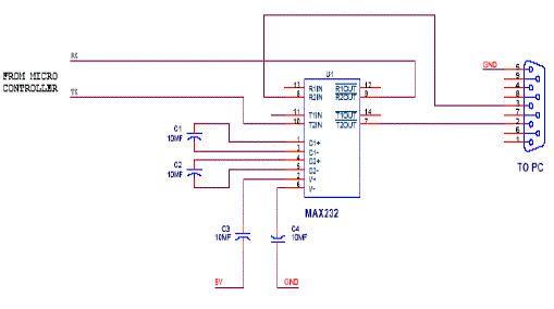
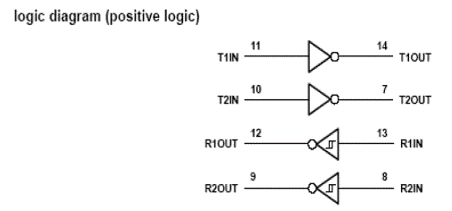
| In this circuit the MAX 232 IC used as level logic converter. The MAX232 is a dual driver/receiver that includes a capacitive voltage generator to supply EIA 232 voltage levels from a single 5v supply. Each receiver converts EIA-232 to 5v TTL/CMOS levels. Each driver converts TLL/CMOS input levels into EIA-232 levels. |
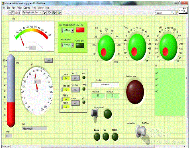
| Here we discuss the front panel used in this project. The Front panel of the LabVIEW program is shown in the figure 7. VISA tools are used for interfacing the software program and the hardware system. VISA resource name is used as a control to mention the port used for communication. The data received from the microcontroller is indicated. Indicators are used to indicate the test conditions. |
i)pH detection
|
| Here pH detection technique used is discussed. |
| Maximum value……7.5……105mV |
| Minimum value…….6.5……80mV |
| When pH value is less than 6.5 or greater than 7.5 pollution level is indicated and it is reported to pollution control board through GSM technology and a motor gets on automatically. |
ii)Temperature detection
|
| Here the temperature detection technique adopted is discussed. |
| Maximum value……40OC |
| When temperature value is greater than 40OC pollution level is indicated and it is reported to pollution control board through GSM technology and fan gets on automatically. |
iii)Carbon monoxide detection
|
| Here CO detection technique used is detected |
| Maximum value……200ppm……150mV |
| When CO value is greater than 200ppm pollution level is indicated and it is reported to pollution control board through GSM technology and an alarm gets on automatically. |
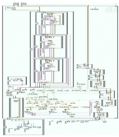
B) BLOCK DIAGRAM OF THE SYSTEM
|
| If the condition for communication is enabled, the data received from the microcontroller .The strings are converted to numeric data which is represented in front panel. |
| The field of pollution monitoring and control is very wide and this project is an attempt to minimize the problem of cost and regular inspections by the utility of Global System for Mobile communications. For alleviating these problems, advanced GSM system with LabVIEW is used. The performance and robustness of the pollution monitoring and control system can further be improved by implementing sensors for controlling dust, noise, smoke, moisture and other parameters, thereby improving the industrial and natural environment. |
| |
Figures at a glance
|
 |
 |
 |
 |
 |
| Figure 1 |
Figure 2 |
Figure 3 |
Figure 4 |
Figure 5 |
 |
 |
 |
 |
| Figure 6 |
Figure 7 |
Figure 8 |
Figure 9 |
|
| |
References
|
- S.R.N. Purnima Reddy, ‘‘Design of Remote Monitoring and Control System with Automatic Irrigation System using GSM-Bluetooth,’’ inInternational Journal of Computer Applications , Volume 47, No.12, pp. 12-25,2012.
- A. Lay-Ekuakille,P.Vergallo, and N.I.Guannoccaro ‘‘Prediction and validation of outcomes from air monitoring sensors and network of sensors,’’ inProceedings of the 5th International Conference on Sensing Technology, pp. 73-78,2011.
- V.Ahmed,‘‘Innovative cost effective approach from cell phone based remote controlled embedded system for irrigation,’’ in proceedings ofInternational Conference on Communication Systems and Network Technologies, pp. 419-424,2011.
- GhainmAlwan, and Farooq Mehdi. ‘‘Study the stability of a wastewater treatment unit using LabVIEW,’’ Chemical Engineering Department,University of Technology/chemical Eng. Department, Tikrit journal for science & Technology, pp. 56-62,2011.
- Jifeng Ding, Jiyin Zhao, and Biao Ma.‘‘Remote monitoring system of Temperature and Humidity based on GSM,’’ in proceedings of 2ndInternational Conference on Computational Intelligence and Industrial Application, pp. 678-681,2008.
- N.Kularatna,andB.H.Sudantha, ‘‘An environmental air pollution monitoring system based on the IEEE 1451 standard for low cost requirements,’’IEEE Sensors Journal, volume 8, pp. 415-422,April 2008.
- Chen Peijiang and Jiang Xuehua. ‘‘Design and Implementation of Remote Monitoring System Based on GSM,’’ Pacific-Asia Workshop onComputational Intelligence and Industrial Application, volume 15, pp. 678-681,2008.
- Y.Ma, M.Richards, M.Ghanem, Y.Guo, and J.Hassard, ‘‘Air Pollution Monitoring and Mining Based on Sensor Grid in London,’’Sensors, volume13, pp. 3601-3623,2008.
- J.Elson, and A.Estrin, ‘‘Sensor networks: a bridge to the physical world,’’ Wireless Sensor Networks, volume 9, pp. 3-20,2004.
- N.Xu, ‘‘A Survey of the Sensor Network Applications,’’ IEEE Communications Magazine, Volume 40, No.8, pp. 102-114,2002.
- G.Krhoda, ‘‘Nairobi River Basin Project Phase II: The Monitoring and Sampling Strategy for Ngong/MSotoine River,’’ In press, pp. 55-58,2002
|