In this paper a new reference generation technique to integrate renewable energy to the grid is proposed. The increase in power demand is met by the renewable energy and distributed generation. The power electronic components are widely used to mitigate the current harmonics, reactive power compensation and regulate load voltages. This converters require a DC link which is supplied from the renewable energy resources (solar and wind). This hybrid renewable energy resources act as the voltage source and they also inject active power generated by the renewable energy resources. In this paper a active compensator is used to compensate the reactive power, reduce harmonic in the source current and injects the active power from the renewable energy resources to the grid. This simulation studies are carried out and analyzed for single phase using MATLAB/ SIMULINK tool
Keywords |
| Terms-Distribution Generation (DG) , Solar Photovoltaic(PV),Total Harmonic Distortion(THD),Hybrid
Renewable EnergySystem(HRES) . |
INTRODUCTION |
| Indian power sector is facing challenges and despite significant growth in generation over the years, it has been
suffering from shortages and supply constraints. Energy and peak load shortages were 7.8 % and 13 % respectively in
the year 2012-03. The per capita electricity consumption in India is about 400 kWh/year, which is significantly lower
than the world average of around 2,100 kWh/year. As GDP growth accelerates to an ambitious 8 to 10 %, the shortage
of power will become more severe. With reference to above power and energy scenario, Ministry of Power (MoP) and
Ministry of Non-conventional Energy Sources (MNES), Government of India, has been promoting viable renewable
energy technologies including wind, small hydro and biomass power, energy conservation, demand side management
etc. MNES has been promoting various sources of renewable energy since 2000. Out of total existing generation
capacity, nearly 72% is contributed by thermal power. With a need for sustainable economic growth, the Government
of India, through the Ministry of Non-Conventional Energy Sources (MNES), is encouraging and catalysing the growth
of renewable energy based power including biomass, wind, hydro, solar photo-voltaic etc. It is expected that a judicious
mix of centralised fossil fuel power plants and decentralised renewable energy based power plants will lead to an
environmentally friendly augmentation of the power sector in India. |
| Electrical load of modern power systems contain the combination of linear and nonlinear loads. In recent years, use of
solid state electronics, as switching devices of power electronic converters are being increased vastly. As a result,
power system networks are subject to high level of harmonics. Although, the fast-switching power electronics devices
have several advantages, these systems suffer from the problem of drawing harmonics and reactive component of
current from the sources and offer highly nonlinear characteristics. The currents drawn by these electrical loads have a
wide spectrum that includes: fundamental reactive power, third, fifth, seventh, eleventh and thirteenth harmonics in
large quantities and other higher frequency harmonics in small percentage. |
| One of the well known methods to generate electricity on plant is installing a Distributed Generation (DG). As a list
of distributed generators one can refer to synchronous and combustion turbines which functions with high-energy fossil |
| fuels such as oil, propane, natural gas, gasoline or diesel, and wind turbines. It is predicted that Distributed Generation
(DG) will be common in futures power systems as a result of the existence of a large demand of generating electricity
from renewable energy resources such as wind power, biogas, and Photovoltaic (PV). |
| In this paper we use shunt converter to inject the active power to the grid from the distributed hybrid renewable
source and simultaneously the shunt converter also perform the reactive power compensation and reduce the current
harmonic distortions. The reference generation is based on the instantaneous power theory. The simulation studies are
carried out with the hybrid renewable source of energy. |
DISTRIBUTED GENERATOR USING SHUNT CONVERTER |
| In general, DG can be defined as electric power generation within distribution networks or on the customer side of
the network which are physically distributed. The flow of power in the distributed generation system is bidirectional
that the power can flow from the grid to the load and when the power is generated by the distributed generation like PV
system, wind energy system or fuel cell is of sufficient quantity the power can be feed back to the grid. The power
generated from the PV system can be directly connected through the DC-AC converters to the AC bus of the grid as a
shown in Fig. 1 |
| Alternative design is based on using a DC-DC boost converter to step up the DC voltage and extract the available
maximum power, and then the use of DC-AC converters . Normally the grid connected load used in the distributed
system is single phase, therefore the use of single phase in verter topology is more important. The single phase inverter
can be used in domestic purpose so by putting a small distributed generation like PV panels on the roof top of the house
s and commercial buildings, this energy can be feed to the grid by a large number of PV panels to pull out large amount
of electrical power onto the grid. |
| B. Sola r PV Module |
| Incident sunlight can be converted into electricity by photovoltaic conversion using a solar panel. A solar panel
consists of individual cells that are large-area semiconductor diodes, constructed so that light can penetrate into the
region of the p-n junction. The junction formed between the n-type silicon wafer and the p-type surface layer governs
the diode characteristics as well as the photovoltaic effect. Light is absorbed in the silicon, generating both excess holes
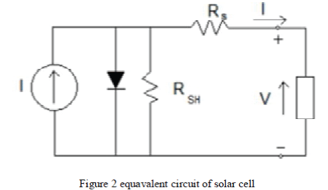
and electrons. These excess charges can flow through an external circuit to produce power. Figure 2 shows the
equivalent circuit to describe a solar cell. The diode current is given as |
 |
| It is clear that the current I that flows to the external circuit is |
 |
| where ISC is short circuit current, I0 is the reverse saturation current of the diode, and A is temperature-dependent
constant, A=q/kT [1]. If the solar cell is open circuited, then all of the Isc flows through the diode and produces an open circuit voltage Voc of about 0.5-0.6V. If the solar cell is short circuited, then no current flows through the diode, and all
of the short-circuit current Isc flows through the short circuit. |
| Since the Voc for one solar cell is approximately 0.5-0.6V, then individual cells a panel” to produce more usabl levels.
Most solar panels are made to charge 12V batteries and consist of 36 individual cells (or units) in series to yield panel
Voc -20V≈18.The voltage for maximum panel power output is usually about 16-17V.Each 0.5-0.6V series unit can
contain a number of individual cells in parallel, thereby increasing the total panel surface area and power generating
capability. |
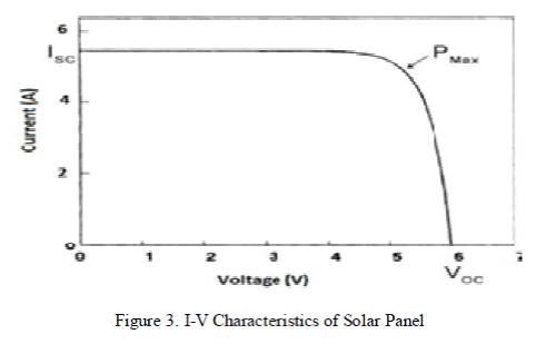
| Figure 3 illustrates the I-V curve and power output of a solar panel. If no load is connected with solar panel which is
sitting in the sun, an open circuit voltage Voc will be produced but no current follows. If the terminals of the solar panel
are shorted together, the short-circuit current I SC will flow but the output voltage will be zero. In both cases, no power
is delivered by the solar panel. When a load is connected, we need to consider the I-V curve of the panel and the I-V
curve of the load to figure out how much power can be delivered to the load. The maximum power point (MPP) is the
spot near the knee of the I-V curve, and the voltage and current at the MPP are designated as Vm and Im. For a
particular load, the maximum point is changing as the I-V curve is varying with the temperature, insolation, and
shading. Because solar power is relatively expensive, it is important to operate panels at their maximum power
conditions. In fact DC-DC converters areoften used to “match” the loa equivalent resistance of the panel to maximize
the power from the converter. |
| C. Wind Turbine Model |
| The wind turbines are classified in to two types based on their speed namely Fixed speed wind turbines and
variable speed wind turbines. The fixed speed wind turbines uses the induction motor on the other hand the variable
speed wind turbine uses Doubly Fed Induction Generator (DFIG) and Permanent Magnet Synchronous Generator
(PMSG). This type of variable generator uses two converters machine side converter and grid side converter. Thin type
of turbine are used to connect the generated power to the grid. The operating speed of variable speed wind turbine varies from 1000-1500 rpm. |
| The grid side converters are rectifiers which converts the generated power into DC and on the other side the
grid side converter uses the inverter which converts the DC power into AC power. The grid side converter uses pwm
inverters which used to reduce the harmonic generated due to the conversion and the power in injected to the grid. Hear
the PMSG generator is used to convert the kinetic energy present in the wind is to electric energy. The simple model of
PMSG present in the MATLAB/SIMULINK is used to model the wind turbine. The basic equation of the wind turbine
are given below. |
| The stator flux-linkage equation are |
 |
| In the PMSM torque of the motor plays the major role and also the speed of the wind. The variables in the power
generation are the torque and the wind speed. If this two parameters are varied in the Simulink model the output power
also varies proportionally. |
REFERENCE CURRENT EXTRACTION |
| In literature the reference generation for three phase is widely used to generate the reference current for the control of
converter using synchronous frame theory and instantaneous reactive power theory The instantaneous power theory is
also used in the reference generation of the single phase converter using p-q theory. The d-q theory is generally used
for the reference current generation in three-phaseThe instantaneous power consumed by the load is give by |
 |
| This power is then passed through a low pass filter or a moving average filter to filter out the oscillatory component of
the power. The net real component of the current required to from the source can be written as |
| Ilp= ( Pavg - Ppv)/Vrms (11) |
| The maximum power generated by the PV system P pv is subtracted from the average power to find out the net real
component of the current given by (7). The ilp must be phase-locked with the voltage so that the phase between current
and voltage must be same for unity power factor. The required compensating current ic(t).can be calculated by
subtracting the ilp (or iref(t)) from the load current il(t), as defined by (9). |
SIMULATION RESULT |
| The simulation is carried out by using power system simulator MATLAB/SIMULINK. The simulations are carried out
for a shunt converter to inject active power and load reactive and harmonic compensation. The load considered is a
rectifier type non-linear load connected in series with a R-L elements. |
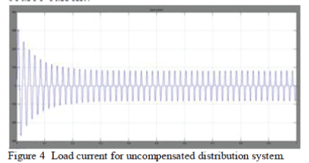
| The figure 4 represents the waveform of the source current. From the waveform we can observe that the waveform of
the source current in distorted due to the non-linear load. As said earlier the generator supplies its power to the nonlinear
load. In the below graph the X-axis represents the time period and the Y-axis represents the amplitude of the
source current. |
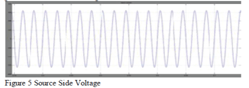
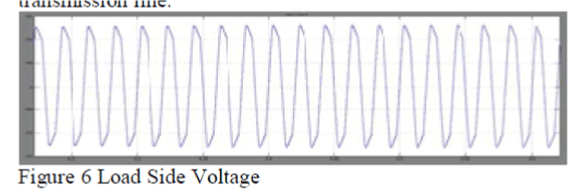
| Now the figure 5 and 6 shows the voltage waveform of the source side and load side voltage waveform. Figure 5 shows
the source side voltage waveform and figure 6 shows the load side voltage waveform. From the wave form it is
observed that there is a phase shift in the load side voltage waveform. this phase shift is due to the presence of the
inductor in the transmission line. |
| In the figure 5 the X-axis represents the time period and Y-axis represents the amplitude of the voltage. The peak to
peak source side voltage is 300v |
| Similarly in figure 6 the X-axis represents the time period and Y-axis represents the amplitude of the voltage. The peak
to peak source side voltage is 280v. We can observe an voltage drop of 20v because of the resistance present in the
transmission line. |
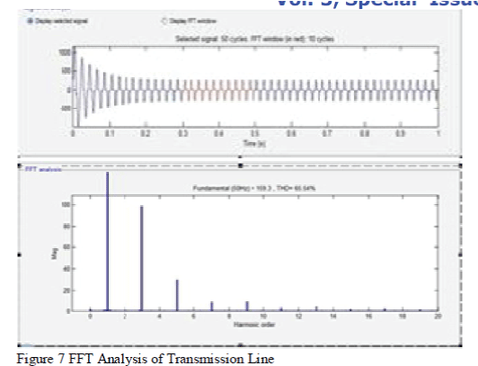
| The figure 7 represents harmonic analysis done in the MATLAB/SIMULINK. The harmonic analysis is done for the
source side current waveform and the start time was taken to be 0.2sec and the no of cycles observed is 30 cycles. The
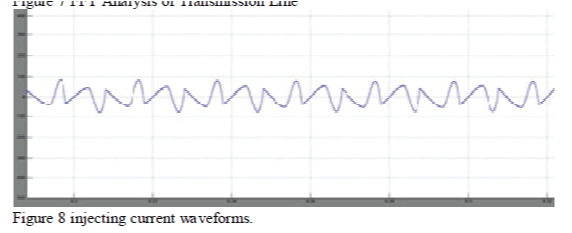
Total Harmonic Distortion was found to be 65.48%. The compensating current is supplied by the shunt converter as
shown in Fig. 8. |
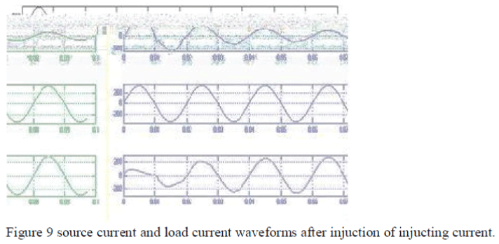
| Figure 10 represents the output waveform of the circuit model shown in the figure 9 hear we can observe that the
source current waveform is sinusoidal. This is sinusoidal because of the impact of the integration of hybrid renewable
energy to the short transmission line. The source voltage and the load voltage waveform does not change it remains
unchanged. For all the graph X-axis is the time period and the Y-axis is the amplitude of voltage. The source current is
in phase with the load voltage so we can obtain unity power factor. |
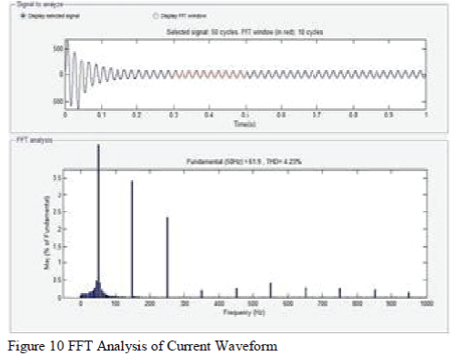
| Figure 10 represents the FFT analysis of the source current after the integration of the hybrid renewable energy to the
transmission line. On executing the the analysis taking the start time period 0.3s for the 30 cycles it was found that the
Total Harmonic Distortion was 4.28%. the graph is shown below |
| The figure 10 represents the harmonic analysis of the source current waveform in which the THD is reduced to 4.27
%.The THD value less than 4% is said that the power delivered is quality power. |
CONCLUSION |
| In this paper the hybrid renewable energy source is integrated by the use of shunt converter. The shunt converter serves
the two purposes successfully, one it improves the power quality problem due to the non linear load like the harmonics
and the reactive power compensation, secondly, it injects the active power generated from the HRSE system. The
results shows with the integration of the HRSE power can be easily done by keeping the source current sinusoidal and
at unity power factor. |
Figures at a glance |
 |
 |
 |
 |
 |
| Figure 2 |
Figure 3 |
Figure 4 |
Figure 5 |
Figure 6 |
 |
 |
 |
 |
| Figure 7 |
Figure 8 |
Figure 9 |
Figure 10 |
|
References |
- M. G. Villalva, J. R. Gazoli, and E. R. Filho, “Comprehensive approa to modeling and simulationIEEETrans. Powerof photovoltaic arrays,” Electron., vol. 24, no. 5, pp. 1198–1208, May 2009
- B. Yang, W. Li, Y. Zhao, and X. He, „„Design and analysis of a grid connected photovoltaic IEEETrans. Powerpower system,‟‟ Electron., vol. 25, no. 4, pp. 992--1000, Apr. 2010.
- Z. Chen, J. M. Guerrero,hestateandofthe F. Blaabjerg, “A review of the art of power electronics IEEE Trans. Power for windturbines,‟‟Electron., vol. 24, no. 8, pp. 1859--1875, Aug. 2009.
- B. Singh, K. Al-Haddad and A.Chandra, -“A new control approach to 3phase active filter for harmonics and reactive power compensation”,- IEEE Trans. on Power Systems, vol. 46, no. 5, pp.133 –138, Oct. 1999
- H. Akagi, “Trends in active power line conditioners”,IEEE Trans on Power Electronics, vol.9, no.3,pp.263-268, May.1994
- L.Gyugyi, E C,Strycula,ers”,inProc“Active.ac power filter IEEE/IAS Annu. Meeting, vol.19, pp 529-535, 1976
|