Keywords
|
| DC hybrid system, bidirectional DC-DC converter, Proportional Integral (PI) controller, Photovoltaic (PV), Point of Common Coupling (PCC). |
INTRODUCTION
|
| In many industrial sectors, due to increasing energy demand stand alone hybrid power system is used. High reliability power supply is required for critical loads. During voltage sags or complete interruptions of the power, the energy has to be supplied from local Energy Storage Systems (ESS). Conventional ESS for the hybrid power system is basically relying on the choice of good batteries [1]. There are many disadvantages associated with batteries such as low-power density and limited charge/discharge cycles. |
| Extracting pulsed power instead of average power from the battery can decrease its lifespan. The current variations cause voltage transients that can be interpreted by the low-voltage detection circuit as a discharged battery creating sudden stress in battery. The pulsed currents have a higher Root Mean Square (RMS) value, which might cause increased battery losses. The sudden changes in currents also reduce greatly the battery runtime [2]. |
| A super capacitor is a double-layer electrochemical capacitor that can store more energy than a typical capacitor. It shares the characteristics of both batteries and conventional capacitors and has an energy density about 20% of a battery. Moreover, they have almost negligible losses and long lifespan. They can process a large number of charge and discharge cycles (several hundred thousand cycles) compared to only a few thousand cycles for batteries and can supply much higher currents than batteries [2]. Batteries are mostly efficient when used to supply low, reasonably steady power levels. Super capacitors are very effective in storing charge for later use. Their leakage rate and series resistance are quite small [3]. |
| The power-sharing method between the super capacitors and the battery is combining super capacitors with batterybased hybrid power system gives the best of high energy and high-power configurations. The super capacitors ensure the power impulses and reduce high power demands away from the battery [4]. |
| The full bridge type dual active bridge DC-DC converter topologies for the combination of battery and super capacitor are used in this DC hybrid system [5]. They are very attractive because of their zero voltage switching, low component stresses and high power density features. Moreover, the high frequency transformer with DC-DC converter prevents fault propagation and enables a flexible output/input voltage ratio [6]. Therefore, with a dual active bridge DC-DC converter as the power conditioning system, different types of power sources and energy storage systems can be applied to high DC voltage applications [7]. |
LITERATURE SURVEY
|
| The integration of battery with super capacitor and the power sharing methods used to improve the hybrid system performance and converter technique that connects the battery and the super capacitor with primary system. The topologies of different converters are discussed for the selection of converter. |
| Lijun et al [4] have discussed about an actively controlled battery/ultra capacitor hybrid has broad applications in pulseoperated power systems. A converter is used to actively control the power flow from a battery, to couple the battery to an ultra capacitor for power enhancement, and to deliver the power to a load efficiently. The hybrid can achieve much greater specific power while reducing battery current and its internal loss. The operation of an active hybrid results in a much lower battery current with very small ripples, and therefore a lower battery temperature, which are preferred by many applications for a longer battery lifetime. A compromise should be made between the power enhancement and the discharge cycle time in order to achieve optimized results depending upon applications. |
| Fabrice et al [15] have discussed an experimental control strategy of Photovoltaic (PV) system. This system consists of PV array, DC-DC power converters, electrolytic storage, and programmable DC electronic load. This control aims to extract maximum power from PV array and manages the power transfer through the DC load, respecting the available storage level. The system allows simultaneously supply of a DC load and the charge or the discharge of the storage during the PV power production. Nevertheless, it responds within certain limits of the storage State of Charge (SOC) thresholds. The suggested method operates successfully within the control of a PV stand-alone system but involves an optimized storage sizing and an algorithm able to extract a PV limited power according to the load request and to manage the load shedding. |
| Xie et al [9] have discussed the analysis and modeling of a DC hybrid power system. Hybrid power systems combine multiple complementary power generation and energy storage technologies to achieve a level of system performance that is not possible for those involving a single technology. Complicated dynamic interactions of the hybrid power system elements, coupled with stringent safety, power quality and efficiency requirements, impose challenging coordinating control and dynamic optimization problems. A large signal dynamic model of the DC hybrid power system testbed is developed and validated by experimental results. This model will enable a model based design approach for control development and system integration. |
| Chuanhong et al [5] have focused an isolated three-port bidirectional DC-DC converter composed of three full-bridge cells and a high-frequency transformer is used in this paper. Besides the phase shift control managing the power flow between the ports, utilization of the duty cycle control for optimizing the system behavior is discussed and the control laws ensuring the minimum overall system losses are studied. The dynamic analysis and associated control design are discussed. A control-oriented converter model is developed. The proposed topology and control is particularly relevant to multiple voltage electrical systems in hybrid electric vehicles and renewable energy generation systems |
| Florian and Johann [16] have discussed an accurate power loss model for a high-efficiency dual active bridge converter, which provides a bidirectional electrical Interface between a battery and a High voltage DC bus in a fuel cell car, is derived. In automotive applications, high converter efficiency and high power densities are required. Thus, it is necessary to accurately predict the dissipated power for each power component in order to identify and to properly design the heavily loaded parts of the converter. In combination with measured efficiency values is that conventional converter. |
| Oggier et al [17] have discussed a switching control strategy to control the power flow and minimize the total power losses of the dual active bridge converter topology. The control strategy consists of driving the bridge with the largest DC voltage to generate a three-level Pulse Width-Modulated (PWM) voltage. This PWM is the phase shift between the primary and secondary transformer voltages and the modulation index. An algorithm to control the output power of the DAB topology with maximum efficiency. These variables are calculated using an algorithm that is deduced on the basis of particular calculation and analysis of converter losses. |
DC HYBRID SYSTEM
|
| Hybrid systems are combining two or more modes of electricity generation together, usually using renewable technologies to obtain maximum performance [8]. Hybrid systems provide a high level of energy in generation methods, and the energy storage system is included for smooth power delivery [9]. The energy storage systems are integration of battery super capacitor. The Figure 1 shows the DC hybrid system connected to DC bus. In this hybrid system solar PV system with boost converter regulates the DC voltage and synchronous generator with universal rectifier for conversion from AC to DC to maintain the DC bus. The energy storage devices (Battery and Super capacitor) are connected with dual active bridge DC-DC converter. The DC hybrid system is connected to the DC drive application. |
A. SOLAR PV GENERATION
|
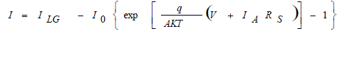
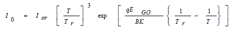
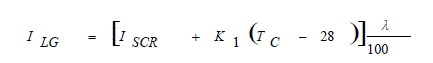
| In this paper the solar PV generation is modeled based on the PV cell characteristics [10]. A boost converter is interfaced between the solar PV and the DC bus to transfer maximum power from PV. The solar PV current is varied according to solar radiation. The duty cycle of boost converter is adjusted to regulate the DC voltage. The solar PV cell characteristics is, |
 (1) (1) |
 (2) (2) |
 (3) (3) |
| where, |
| I - cell output current |
| V - cell output voltage |
| I0 - cell saturation current |
| T - cell temperature in K |
| K/q - boltzmann's constant divided by charge 8.62 x 10⁻⁵ K |
| TC - cell temperature in °C K - temperature coefficient at ISCR 0.0017 C A 0 λ - cell illumination (mW/cm2) |
| ISCR - cell short circuit current |
| ILG - light-generated current |
| EGO - band gap for silicon |
| B - ideality factors (1.92) |
| Tr - reference temperature (301.18 K) |
| Ior - saturation current |
| Rs - series resistance |
| B. BOOST CONVERTER |
| Boost converter is to convert an unregulated DC voltage to a regulated DC output voltage. The Figure 2 shows the circuit diagram of boost converter with maximum power point tracker (MPPT). In solar PV system, the solar output voltage regulated by the boost converter in hybrid system to provide constant voltage. |
| The output power of the PV module changes with solar irradiance and cell temperature. The solar irradiation is unpredictable, which makes the maximum power point of the PV module changes continuously. A MPPT technique is needed to operate the PV module at its maximum power point. The Perturb and observe (P&O) algorithm is one of the MPPT control algorithm which used to generate the gate pulse for the boost converter operation. The P&O algorithm operates by periodically incrementing or decrementing the PV array operating current, and comparing the PV output power with the previous one. If it is positive, the control system moves the PV array operating point in the same direction, otherwise, the direction is changed. |
C. SYNCHRONOUS GENERATOR
|
| The synchronous generator requires the prime mover to rotating the rotor for the generation of electric power. In this paper the synchronous generator with diesel engine has been proposed. The synchronous generators produce electrical energy whose frequency is synchronized with the mechanical rotational speed [11]. |
 |
| where, |
| fe is the electrical frequency (Hz) |
| nm is the rotor speed of the machine (rpm) |
| p is the number of poles |
| The universal bridge rectifier system is modeled to convert AC to DC in order to connect with the DC hybrid system. The universal rectifier includes the controlled or uncontrolled power electronic devices. The uncontrolled power converter is modeled in this universal bridge rectifier [12]. |
INTEGRATION OF BATTERY AND SUPER CAPACITOR
|
| The storage devices are integrated in the hybrid system is mainly to optimize the system performance. The voltage variation in the hybrid system can be compensated by integrating super capacitor with battery. |
| Bidirectional DC-DC converters are used in to connect the battery and super capacitor to the DC hybrid system [5]. The Dual Active Bridge Converter (DAB) is an isolated bidirectional DC-DC converter shown in Figure 3. The high frequency transformer in the DAB converter provides galvanic isolation between the primary and secondary side of the converter. This converter is used to charge and discharge the energy storage bank [13].v |
| A. OPERATION OF DAB |
| The two DAB converters are utilized included for connecting the battery and super capacitor to DC hybrid system. The switches S1 and S2 which are associated with primary side of the transformer T1 is operated at 50% duty cycle. An auxiliary energy source such as battery and super capacitor is connected to the variable low voltage side across the capacitors, C1 and C2. Bidirectional operation can utilized between the auxiliary energy bank and the high-voltage DClink bus. Switches S3 and S4 are controlled by the duty cycle to reduce the current stress. The transformers T1 and T2 with independent primary windings as well as serially connected secondary windings ensures the galvanic isolation and boost a low input voltage to the high voltage DC-link. A DC blocking capacitor Cb is added in series with the primary winding of T2 to avoid transformer saturation caused by asymmetrical operation in full-bridge circuit. The voltage doubler circuit on the secondary side is to increase the voltage conversion ratio. The inductor L2 on the secondary side is utilized as a power delivering interface element between the source side and the high voltage DC-link side. According to the direction of power flow, the converter operation mode that can be defined as boost mode. In the boost mode, the power is delivered from the battery and super capacitor to the DC voltage bus. |
| B. CONTROL LOGIC FOR DAB |
| The Figure 4 shows the control logic diagram to generate the pulse to the DAB converter. The PI controller in the logic diagram is adjusted according to the voltage error. This gain controls the output of the PI controller and the error as the reference signal to the multiple Pulse Width Modulation (PWM). The multiple PWM compares reference signal with triangular carrier signal and generating the pulses to the switches in the bidirectional DC-DC converter [14]. Thus the switching of the converter switches are controlled. |
CHOPPER CONTROLLED DC DRIVE`
|
| In this paper the DC hybrid system is designed to drive the DC motor. The DC motor is operating under various load condition [15].The Figure 5 shown the block diagram of chopper controlled dc drive. The chopper device is utilized for control the speed of the motor. |
| The hysteresis current controller is used to control the motor speed through the chopper device. It compares the sensed current with the reference and generates the gate signal for the chopper to force the motor current to follow the reference value which derived from the current loop. The speed control loop uses a Proportional-Integral (PI) controller which produces the reference for the current loop. |
RESULTS AND DISCUSSION
|
| The model of the DC hybrid system according to the system characteristics is shown in Figure 6 which consists of solar PV model, synchronous generator with AC/DC universal converter. The energy storage devices such as a battery and super capacitor are separately connected to the DC system. The whole system is connected with a common DC-link capacitor. |
| The changes in load torque are applied to the motor as shown in Figure 7 the load torque changes mentions the DC drive operated in the different load applications. The DC-link voltage waveform of DC hybrid system shown in the Figure 8. The voltage level is measured in two different conditions and it’s to be compared the performance result. In the two waveforms shows without energy storage device support and with energy storage device support such as the battery and the super capacitor include by the converter. The battery and super capacitor its deliver voltage to balance the voltage in the DC bus to reduce the voltage fluctuations level. The current variation of integrated battery and super capacitor shown in Figure 9. It shows the discharge level of the current in the battery in figure 9(a) and the discharge level of super capacitor in figure 9(b) the energy storage device supports the hybrid system to mitigate voltage fluctuations. |
| The speed of the motor is shown in Figure 10. The speed of motor under load torque changes shown. The speed is controlled to run the motor in required speed. The speed of the motor measured in two different conditions it shows changes of voltage level the speed of the motor varied. The support of energy storage device connected by the converter it operates in the controlled reference condition. |
CONCLUSION
|
| This paper deals with the energy transfer in a solar PV and Generator to the DC hybrid system. The solar PV system is operated at the maximum power point. Integrated energy storage device such as batteries and super capacitors are utilized in DC hybrid system. The storage devices are effectively connected using dual active bridge converter. The voltage fluctuation in the PCC of DC bus is actively balanced by controlling the converter. The battery stress is reduced and increases in the performance. |
Figures at a glance
|
 |
 |
 |
 |
 |
| Figure 1 |
Figure 2 |
Figure 3 |
Figure 4 |
Figure 5 |
 |
 |
 |
 |
 |
| Figure 6 |
Figure 7 |
Figure 8 |
Figure 9 |
Figure 9a |
 |
| Figure 10 |
|
References
|
- Alireza.K and Zhihao Li “Battery, Ultra capacitor, Fuel Cell, and Hybrid Energy Storage Systems for Electric, Hybrid Electric, Fuel Cell, andPlug-In Hybrid Electric Vehicles: State of the Art,” IEEE Transactions on Vehicular Technology, Vol. 59, no. 6, pp. 2806-2814,2010.
- Krishna C. M., “Managing Battery And Super Capacitor Resources For Real-Time Sporadic Workloads,” IEEE embedded systems letters, Vol.3, no. 1, pp. 35-36, 2011.
- Thounthong .Ph. Rael.S, and Davat.B, “Energy management of fuel cell/battery/super capacitor hybrid power source for vehicle applications,”Journal in Power Sources, Vol. 193, no. 1, pp. 376-385, 2009.
- Lijun.G, Roger A. Dougal and Shengyi.L “Power Enhancement of an Actively Controlled Battery/Ultra capacitor Hybrid,” IEEE Transactions onPower Electronics, Vol. 20, no. 1, pp. 236-246,2006.
- Chuanhong.Z, Simon D. Round and Johann W. Kolar, “An Isolated Three-Port Bidirectional DC-DC Converter with Decoupled Power FlowManagement,” IEEE Transactions on Power Electronics, Vol. 23, no. 5, pp. 2443-2453. 2008
- Dinesh.S, Donald.H.G and Brendan.P.M, “Enhanced Load Step Response for a Bidirectional DC-DC Converter,” IEEE Transactions on PowerElectronics, Vol. 28, no. 1, pp. 371-379, 2013.
- Daniel.C, Dragan.M and Regan Z, “Design and Control for High Efficiency in High Step Down Dual Active Bridge Converters Operating atHigh Switching Frequency,” IEEE Transactions on Power Electronics, Vol. 28, no. 8, pp. 3931-3940, 2013.
- Daniel.S and Ambra.S “Low Voltage DC Distribution System for Commercial Power System with Sensitive Electronic Load,” IEEETransactions on Power Electronics, Vol. 22, no. 3, pp. 1620-1627, 2007.
- Xie.Y, Sun.J, Miz.C and Freudenbergy.J.S. “Analysis and Modeling of a DC Hybrid Power System Testbed for Power Management StrategyDevelopment,” in Proceeding IEEE Vehicle Power Propulsion Conference, pp. 926-933, 2009.
- Rai.G.D, “Non Conventional Energy Sources,” Khanna Publishers India, 2011.
- Jadric.I, Borojevic.D and Jadric.M, “Modeling and Control of a synchronous generator with an active DC Load,” IEEE Transaction on PowerElectronics, Vol. 15, no. 2, pp. 303-311, 2000.
- Jatskevich. J, Pekarek. S. D, and Davoudi. A, “Parametric average-value model of synchronous machine-rectifier systems,” IEEE TransactionEnergy Conversion, Vol. 21, no. 1, pp. 9-18, 2006.
- Florian.K, Johann.W. K, “Accurate Power Loss Model Derivation of a High-Current Dual Active Bridge Converter for an AutomotiveApplication,” IEEE Transactions on Industrial Electronics, Vol. 57, no. 3, pp. 881-890, 2010.
- Xu.D. Zhao.C, and Fan.H, “A PWM plus phase-shift control bidirectional DC–DC converter,” IEEE Transaction on Power Electronics, Vol. 19,no. 3, pp. 666-675, 2004.
- Fabrice.L, Manuela.S and Issam .H “DC Load and Batteries Control Limitations for Photovoltaic Systems. Experimental Validation,” IEEETransactions on Power Electronics, Vol. 27, no. 9, pp. 4030-4038, 2012.
- Florian.K, Johann.W. K, “Accurate Power Loss Model Derivation of a High-Current Dual Active Bridge Converter for an AutomotiveApplication,” IEEE Transactions on Industrial Electronics, Vol. 57, No. 3, pp. 881-890, 2010.
- Oggier.G, Guillermo.O.G and Oliva.A.R, “Switching Control Strategy to Minimize Dual Active Bridge Converter Losses,” IEEE Transactionson Power Electronics, Vol. 24, no. 7, pp. 1826-1838, 2009.
|