Keywords
|
| Ultra-wideband (UWB); WiMAX; coexistence; emission limits; physical layer model. |
INTRODUCTION
|
| Ultra Wide Band (UWB) systems aim to dominate the short-range wireless communication sector facilitating wireless data transmission at rates as high as 110 Mbits/sec. According to the Federal Communication Committee rules, any signal that occupies more than 500 MHz of bandwidth can be considered as UWB. Such signals have been allocated in a large frequency band (3.1 to 10.6 GHz) for unlicensed use [3], with maximum effective isotropic radiated power (EIRP) of -41.3 dBm/MHz, in order to avoid interference with existing narrowband or wideband devices [1]. Although this PSD (Power Spectral Density) mask can effectively suppress UWB interference to most existing systems operating at frequencies lower than 3 GHz (GPRS, GSM 900, GPS, WCDMA and Bluetooth), there still exist devices, which operate in the ultra wide spectrum allocated for UWB communications, resulting in mutual interference to both systems. |
| One of the system, whose operation could be harmed by UWB interference, is WiMAX system, which is defined by IEEE-802.16 standard. This standard aims to deliver high data rates over large geographical areas to a large number of users [4]. This means that WiMAX will be looking to provide wireless last-mile broadband access with performance comparable to Cable and DSL connections [5]. The operation of WiMAX systems has been restricted in the licensed 2.5GHz, 3.5GHz and license-exempt 5.8GHz. This means that they will share the bands used by UWB systems. So, if UWB technology is to be successful, it is vital for UWB developers. |
| The coexistence scenario analyzed in this work corresponds to the case of an UWB transmitter operating at the same frequency band as a WiMAX receiver. WiMAX, which is derived from the IEEE 802.16 air interface standards [4], allows for high-speed broadband connectivity in point-to-multipoint wireless metropolitan area network (WMAN). In view of the data rate and expected range, WiMAX and UWB can be regarded as complementary radio technologies which may coexist in a near future [5]. |
| The coexistence has been studied evaluating the interference in downlink considering an 802.16e WiMAX system as a victim of UWB communication and, the experimental results indicated that a victim WiMAX (with 5 MHz and 10MHz bandwidth) QPSK and 16-QAM modulation technique exhibit proper operation up to 1 meter transmission in presence of UWB interference if a protection margin of 1m is met.and analyze the BER. |
| In this paper, the effect of UWB interference on WiMAX downlink system. has been studied and proposed the minimum requirements for WiMAX to perform well and overcome the UWB interference. |
| The paper is organized as follows: section II presents the WiMAX simulator, the UWB simulator is discussed in section III. In section IV, discussed the interference scenario between UWB and WiMAX, while the simulation results are discussed in section V. Finally, the conclusions are drawn in section VI. |
WIMAX PHYSICAL LAYER SIMULATOR
|
| The simulator is based on fixed WiMAX system which differs from mobile WiMAX by its very wide coverage area, in which one base station can cover a small city. While for mobile WiMAX, one base station can cover only about 600 m cell range. |
| However, the fixed WiMAX physical layer is based on various communication techniques including coding, interleaving, QPSK modulation, 16-QAM modulation and OFDM transmission. In this section, we elaborate the physical layer of WiMAX downlink system throughout exploring the WiMAX simulator. |
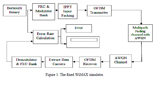
| The WiMAX system model employed in this work follows the specifications of IEEE802.16e standard for Wireless MAN fixed wireless access networks [2]. This system is based on OFDM with 256 subcarriers, of which 192 are used for data processing, 8 are pilot subcarriers, 1 is zero Direct Current (DC) subcarrier and 55 are nulled for guard band protection. WiMAX defines possible cyclic prefix intervals of 1/4, 1/8, 1/16 and 1/32 of the FFT symbol duration. The simulator employs a guard interval of 1/8. Table I summarizes the main relevant parameters for WiMAX PHY model. WiMAX endto- end simulation model is shown in Fig.1. |
| Transmitter, a robust Forward Error Correction (FEC) technique is employed based on a concatenation of an outer Reed-Solomon encoder and an inner convolution encoder with compatible rate. The FEC options are paired with several modulation schemes to form burst profiles of varying robustness and efficiency. In our case, QPSK is selected as the modulation scheme with overall code rate 1/2. |
| The output of the QPSK modulator and 16-QAM modulation is the input of the IFFT input packing where pilot tones and the zero DC subcarrier between data are inserted as the first step to construct an OFDM symbol. |
| The WiMAX channel has been modeled as a Multipath Rayleigh fading channel with additive white Gaussian noise (AWGN). The receiver implementation is an inversion of all the transmitter functions with addition of channel estimation based on the pilots and trainings. |
MB-OFDM UWB SYSTEM
|
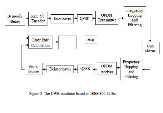
| In this work, the MB-OFDM UWB system is modelled in the indoor case following the ECMA-368 standard. The available 7.5 GHz bandwidth is divided into 14 sub-bands, each having a bandwidth of 528 MHz.. The data rate values fixed by the standard are 53.3, 80, 106.7, 160, 200, 320, 400 and 480 Mb/s. These data rate values are obtained by selecting different combinations of modulation scheme and coding rates. The MB-OFDM PHY layer model setup in the work is shown in Fig.2. |
| The model implements the baseband multicarrier modulation with band hopping, where the coding rate value is obtained at the output of a convolution coding and puncturing block with the value Rc = 5/8; Quadrature Phase Shift Keying (QPSK) modulation scheme is implemented for data rates of 200 Mb/s; the baseband signal is generated in the OFDM transmitter and the OFDM signals are finally transmitted by adopting frequency hopping. |
| A. UWB Channel Model |
| The modified Saleh and Valenzuela (S-V) multipath channel model, which is proposed as the UWB indoor multipath channel model by IEEE 802.15. SG3a is adopted as the channel model for UWB systems. The WiMAX channel has been modeled as a Multipath Rayleigh fading channel with additive white Gaussian noise (AWGN). The receiver implementation is an inversion of all the transmitter functions with addition of channel estimation based on the pilots and trainings. |
UWB INTERFERENCE JOINING
|
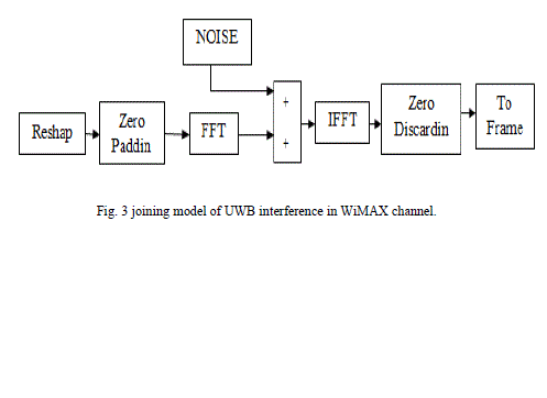
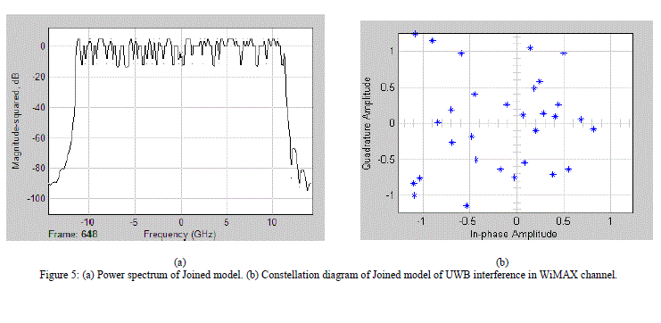
| Once the entire physical layer models of UWB and WiMAX systems are set up, UWB interference can be introduced into the WiMAX system in the form of the channel additive noise, by means of signal processing in the frequency domain. The WiMAX channel is built in the simulator by a Simulink block implemented as a Mat lab m-file. The block diagram of the UWB interference joining is depicted in Fig.3. |
| In Fig.3, the “Reshape” block arranges the input data transmitting over the communication channel in a matrix form, where the corresponding number of rows is calculated from the transform length of WiMAX signal that enables the equal frequency interval between two system signals, as specified in above. Zero padding at the end is performed to achieve a length of 2r (where r is an integer number) bytes for each block to conduct FFT operation. The zero tails is discarded after performing IFFT operation of the mixed signals. To end, the output signal is transmitted over the WiMAX channel in the frame-based mode. |
SIMULATION RESULTS AND ANALYSIS
|
| Other additional parameters used in the simulation are set as follows: |
| 1) WiMAX receiver sensitivity is set to be - 95dBm, the reference distance of interference is R = 1 m and SNR is set at 9.6dB. |
| 2) MB-OFDM UWB: Sampling time is 7.0833×10⁻⁹s, the initial phase of QPSK is π/4, the length of FFT/IFFT is 128- point, and cyclic prefix is 61-point. |
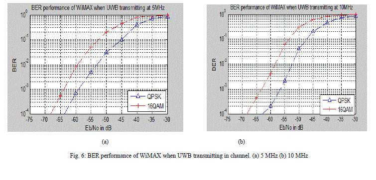
| Fig. 6 (a) shows the BER performance curves of WiMAX system with different modulation of QPSK and 16- QAM respectively in the presence of UWB interference transmitting in channel at 5MHz bandwidth. |
| Assume the BER limit of WiMAX systems is set 0.1% which can adequately meet the communication demands for the victim system, and then from Fig. 6 (a) and (b), we can obtain the reference emission limits for UWB systems, is, -58, -55 dBm/MHz. |
CONCLUSION
|
| In this paper, an efficient numerical method based on the entire physical layer model are presented for interference investigations, of MB-OFDM UWB operating at 3.5 GHz WiMAX band were obtained. Since the scheme takes full consideration of the entire physical structure and technical characteristics of UWB and WiMAX systems, as well as the realistic UWB channel, the physical layer model method can thoroughly reflect the effect of the actual systems. The conclusion may provide a solution to the coexistence between UWB and WiMAX system at 3.5GHz band and have some reference values for the development of UWB spectrum plan. Further works will include more research to consolidate the results along with the evaluation of aggregate effects on the WiMAX downlink performance. |
Tables at a glance
|
 |
 |
| Table 1 |
Table 2 |
|
Figures at a glance
|
 |
 |
 |
| Figure 1 |
Figure 2 |
Figure 3 |
 |
 |
 |
| Figure 4 |
Figure 5 |
Figure 6 |
|
References
|
- D. Porcino and W. Hirt, “Ultra-wideband radio technology Potential and challenges ahead,” IEEE Commun. Mag., vol. 41, No. 7, pp. 66-74,Jul. 2003
- Electronic Communications Committee (ECC), “The protection requirements of radio communications systems below 10.6GHzfrom genericUWB applications,” ECC, Helsinki, ECC Report 064, Feb. 2005
- J. Perez, M. Beltran, M. Morant and R. Llorente. “Protection Margins for Joint Operation of WiMAX 802.16e and WiMedia defined UWBRadio in Personal Area Networks,” IEEE International Conference on Ultra-Wideband 2009, pp. 723-727, Sep. 2009.
- Y. K. Yoon. “Effective Method of Interference Mitigation for UWB Cooperation with WiMAX,” International Conference on AdvancedCommunication Technology 2010, vol. 1, pp.329-332,Feb. 2010
- E. Cano, A. Rabbachin, and J. Fortuny, “Performance analysis of WiMAX systems in the presence of MB-OFDM UWB interference,” 6thInternational Symposium on Wireless Communication Systems, vol.5, pp.264-268, , 2009.
- A.Rahim and S. Zeisberg. “Evaluation of UWB Interference on3.5 GHz Fixed WiMax Terminal,” 16th Mobile and Wireless CommunicationsSummit, vol. 14 pp.1-5, Jul. 2007.
- M. Z. Win, R. A. Scholtz. “Ultra-wide Bandwidth Time-Hopping Spread Spectrum Impulse Radio for Wireless Multiple-AccessCommunications,” IEEE Trans. Commun., vol.48, Apr. 2000.
- Lu Feng, Bin Li, WeixiaZou, Zheng Zhou, Xiaojun Huang “Interference Analysis for UWB Coexistence with 3.5GHz WiMAX System” IEEE Trans. Commun, vol.48 pp 288-291 dec.2010.
|