Keywords
|
| Rectifier, Inverter, PI controller, Fuzzy Logic controller, PMSM motor, Vector control |
INTRODUCTION
|
| World-wide intensive research in the field of advanced control schemes for drives has been performed during the last few years. Now-a-days energy saving has become an increased concern in industrial applications. Manufacturers across many industries are placing increased emphasis on machine designs that support sustainability initiatives and drive financial affluence. Machines that recover safety, diminish waste, ingest less energy and convey supreme arrival on investment are critical to the accomplishment of any maintainable creation. Building such a machine needs a holistic attitude analysing effective proficiency, protection, functionality, yield, material custom, comfort of operation and preservation. Electrical motor drives are a key factor to realize this goal, and among the numerous existing options, the market of industrial drives for low- and medium power applications is extra difficult to proposal as several applications do not involve high concert. Induction motors are the most extensively used in domestic, profitable and various industrial requests. Mostly, the squirrel cage type is characterized by its ease, robustness and low cost, which has constantly finished it very attractive, and it has consequently captured the leading place in manufacturing sectors. As a result of its extensive usage in the industry, induction motors ingest a significant percentage of the complete produced electrical energy. The minimization of electrical energy ingesting through an improved motor design becomes a major anxiety. |
| The Existing method labels the design of a sensor less controller a 3-phase BLDC motor drive with integrated Back- EMF for Zero crossing; with slight cost and best operating efficiency. Currently more and more variable speed drives are designed into pump products to increase product concert and structure efficiency. The low dynamic drive, where the load or speed is changed quite slowly in evaluation with the system mechanical time constant, is a clarification for many common pumps applications since simple algorithms can achieve the control tasks. This paper delivers an essential mathematical method for modelling, torque scheming and control concept of the offered in the drive. |
PROPOSED METHODOLOGY
|
| AC induction motors are seamless for most industrial and commercial uses since of their simple structure and low number of parts, which diminish preservation cost. Induction motors are often used for both constant-speed and adjustable speed drive (ASD) applications. The two basic parts of an induction motor are the stationary stator positioned in the motor frame and the rotor that is free to rotate with the motor shaft. Now motor strategy and construction are extremely superior. For example, stator and rotor laminations have been planned to realize maximum magnetic density with minimum core losses and heating. The basic simplicity of this design approves high efficiency and makes them easily variable to a variation of shapes and enclosures. A three-phase induction motor can finest be understood by probing the three-phase voltage source that influences the motor. Three-phase currents graceful in the motor leads initiate a rotating magnetic field in the stator coils. This magnetic field constantly pulsates across the air gap in the rotor. Equally magnetic flux cuts diagonally the rotor blocks, a voltage is tempted in them, much as a voltage is desirous in the secondary winding of a transformer. To keep these currents to a least, the stator and rotor cores are made of thin steel discs called laminations. These laminations are treated with insulating varnish and then edge welded composed to form a core. This type of core construction greatly diminishes eddy current losses, but does not completely eradicate them. By changing the design of the basic squirrel-cage motor, almost any specific of speed, torque, and voltage can be controlled by the prosperous. |
A. BLDC Motor Drives
|
| Brushless Direct Current (BLDC) motors are one of the motor kinds rapidly accomplishment popularity. BLDC motors are used in manufactures such as Appliances, Automotive, Aerospace, Buyer, Medical, Industrial Automation Apparatus and Instrumentation. As the name suggests, BLDC motors do not use brushes for commutation process instead of that they use electronic commutation. BLDC motors have several leads over brushed DC motors and induction motors. A Brushless DC motor has a permanent magnet rotor and a wound stator. Likewise, there are two types of brushless motors; this type has an exterior rotating magnet inside the inmost rotating magnet assembly. |
| In a brushless DC motor the situation of the coils (phases), with respect to the permanent magnet field, are recognized and the current switched electronically (commutated) to the proper phases. Hall Effect sensors are obviously used to sense the rotor location. Else, sensor less techniques can also be used. BLDC motors are a category of synchronous motor. This revenues the magnetic field created by the stator and the magnetic fields produced by the rotor rotate at the same frequency. BLDC motors do not practice the "slip" that is generally realized in induction motors. BLDC motors originated in single-phase, 2-phase and 3-phase supplies. Corresponding to its type, the stator has the similar number of windings. Out of these, 3-phase motors are the utmost common and generally used in most of the applications. |
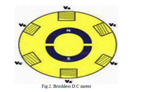
| Fig.2 explains the stator with rotor arrangement of a permanent magnet D.C motor. In this motor the rotor are made of magnets rather than windings in other machines. |
IMPROVED VECTOR CONTROL
|
| The Field Orientated Control (FOC) consists of controlling the stator currents denoted by a vector. This control is based on estimates which alter a three phase period. Then speed dependent structure into a two co-ordinate (d and q coordinates) time invariant scheme. These estimates lead to an assembly associated to that of a DC machine control. Field orientated precise machines vital two constants as input references: the torque factor (aligned with the q co-ordinate) and the flux element (aligned with d co-ordinate). As Field Orientated Control is purely based on predictions and then the control structure switches instantaneous electrical extents. This makes the control precise in every occupied operation (steady state and transient) and liberated of the imperfect bandwidth mathematical model. The FOC thus solves the typical pattern problems, in the following ways: |
| 1. The simplicity of reaching constant reference (torque essential and flux factor of the stator current). |
| 2. The comfort of applying direct torque control. |
A. Vector Control
|
| The electrical DC drive schemes are still used in an extensive range of industrial applications, though they are less reliable than the AC drives. Their benefit consists in humble and precise command and control assemblies. The AC drives, occasionally more expensive but far more reliable. The design of a control scheme is appreciated in two important steps: |
| 1. The drive system has to be transformed into a mathematical model, in order to realize the analysis and the assessment of the system. |
| 2. The imposed response of the drive system is gained through an optimal regulator, when exterior perturbations are existent. |
B. Rotor Flux Orientation
|
| The purpose of vector control is typically to decouple the stator current is into its flux making and torque producing components in order to get a decoupled control of flux and the electromagnetic torque. For this motive a special reference frame is nominated fixed to different space vector variables. The reference frame has to be synchronous; as all the space vectors have the identical angular velocity agreed by the supply voltage frequency mostly, the term of vector control is allied with field orientation control. This resource that the superior synchronous reference frame is connected to one of the flux linkages space vectors. Though, for vector control schemes there are two more options, allied to the currents space vectors: stator and rotor currents. All of these control plans are inspected in this chapter, according to the modelling fact of view of the induction machine. |
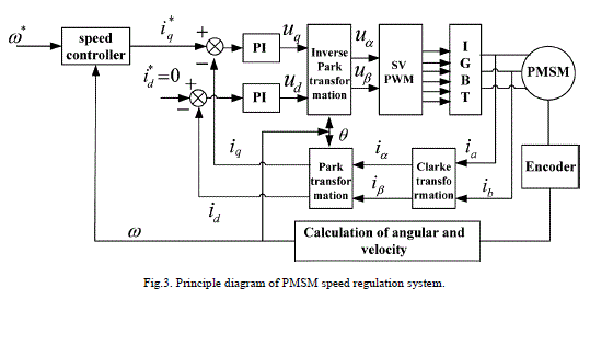
| Fig.3. Shows the PMSM speed control and torque control arrangement with speed controller unit by using the transformation theory .An easy to follow steps algorithm for employing vector oriented control schemes is attained as follows: |
| 1. A whole mathematical model of the three-phase induction machine is established in stationary reference frame, rendering to the chosen set of state-space variables; |
| 2. The rotor based variables are entirely uttered in the new state-variable system; |
| 3. The rotor angular velocity wr term is relieved with (w r - w k) where w k is the angular. |
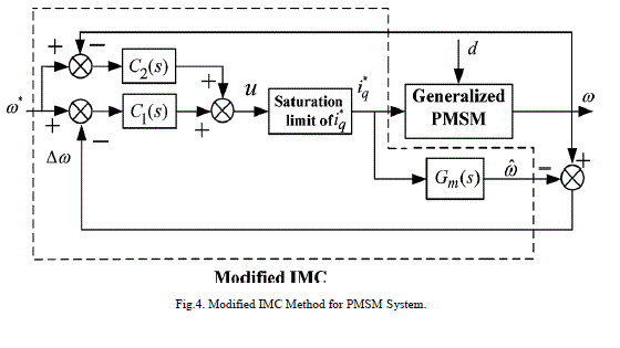
| Fig.4 explains the modified IMC method for a PMSM System. This modified arrangement is used in this proposed methodology for speed and torque control of the motor for the effective operation with reduced losses in motor. |
SIMULATION RESULTS AND DISCUSSION
|
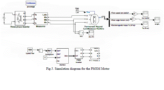
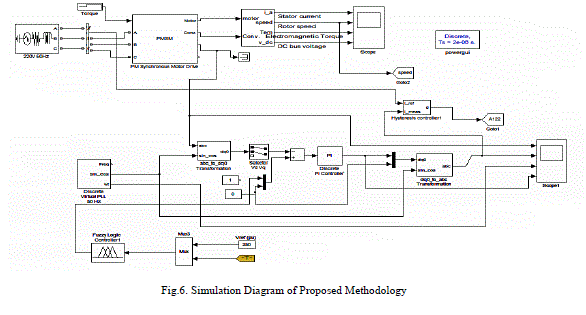
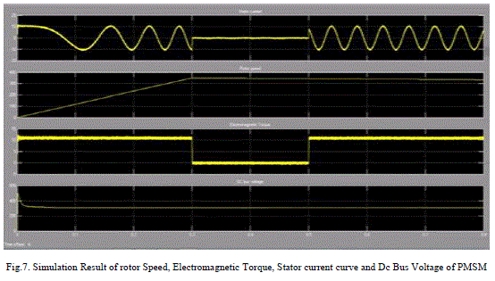
| In this chapter, the simulation result for the PMSM using modified Internal Model control is shown. The MATLAB Simulink tool is used to simulate the results. The building blocks are designed in Simulink. This tool is used to evaluate the PMSM Motor parametrs such as stator current, electromagnetic torque rotor speed and DC bus voltage. |
| Fig.5 ensures the simulation diagram of permanent magnet synchronous motor. This simulation shows the complete arrangement of the PMSM motor control and operation unit. |
| The complete simulation diagram of the proposed methodology using fuzzy and PI controller is shown in Fig.6. |
| Fig.7 shows the simulation output of the stator current curve, rotor speed curve, DC voltage and electromagnetic torque curves of the suggested BLDC motor. |
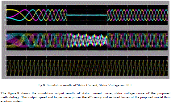
| The figure.8 shows the simulation output results of stator current curve, stator voltage curve of the proposed methodology. This output speed and toque curve proves the efficiency and reduced losses of the proposed model than existing system. |
CONCLUSION
|
| This proposed BLDC drive is more efficient than the Induction motors .This BLDC motor which improves the speed, efficiency, cost and life of the motor because of reduced losses. In this paper, the three phases brushless direct current motor (BLDC) uses a improved vector control unit for speed and torque control of the motor.. A fuzzy adaptive law based on IMC method is established based on experimental check. MATLAB Simulation tool is used in this proposed Method. The output of the simulation explains the BLDC performance with vector control. Hence this modified vector control improves efficiency, torque and reduces losses in this system. |
Figures at a glance
|
 |
 |
 |
 |
| Figure 1 |
Figure 2 |
Figure 3 |
Figure 4 |
 |
 |
 |
 |
| Figure 5 |
Figure 6 |
Figure 7 |
Figure 8 |
|
References
|
- Haider Hussein Kadhim “Technical and Economic Design of Three Phase Induction Motor Using the Multi criterion Optimization Method”Journal of Babylon University/Engineering”.
- Moumita Deb “Control of Voltage Source Inverter for Adjustable Speed Drive”-A Study Report Ind. J. Sci. Res. And Tech. 2013 1(1):1-3/Deb.
- Fundamentals of Polyphase Electric Motors By Lincon Electric Motor.
- Improving Motor and Drive System Performance: A Sourcebook For Industry.
- M.Rakesh and P.V.R.L. Narasimham “ Different Braking Techniques Employed To A Brushless Dc Motor Drive Used In Locomotives”International Electrical Engineering Journal (Ieej) Vol. 3 (2012) No. 2.
- Shubham Mittal, Varun Kumar Gupta and Prof. R. Sudha “Implementation and Realization of Brushless DC Motor International Journal ofScientific& Engineering Research, Volume 4, Issue 6, June-2013 IJSER
- Vivek Kota, VishnuvardhanPasumarthi and YadithyaTangirala “Implementation of Different Speed Control Strategies of BLDC MotorTransactions on Engineering and Sciences Vol. 2, Issue 7, July 2014.
- Sensorless Field Oriented Control of 3-Phase Permanent Magnet Synchronous Motors Using TMS320F2833x-Application Texas ins. July 2013.
|