Keywords |
| Enhanced Adaptive ACKnowledgment (EAACK); Digital Signature; Digital Signature Algorithm (DSA);
Mobile Ad hoc NETwork (MANET); Ad-hoc On demand Distance Vector (AODV); Advanced Encryption Standard
(AES); Routing Overhead (RO). |
INTRODUCTION |
| A mobile ad hoc network (MANET) is a one of the wireless method. The devices are moving in randomly different
directions and communicating with one to another within each nodes communication range. To extend the nodes
communication range, the other nodes in the network act as routers. Thus, the communication may be occurring via
multiple intermediate nodes between source and destination. MANETs have a wide range of applications, specifically in
military operations and emergency and disaster relief efforts [8], [10]. |
| The open network and remote distribution method of MANET make it vulnerable to various types of attacks. For
example, the nodes environmental protection, malicious attackers can easily capture and compromise nodes and make
attacks. Most of the routing protocols in MANETs assume that every node in the network behaves cooperatively with other
nodes and presumably not malicious attackers can easily compromise MANETs by inserting malicious or no cooperative
nodes into the network. An intrusion detection system (IDSs), which is used to detect and mention an attack after it is
accrued, this systems are very important to MANET’s security. |
II. BACKGROUND |
A. Cryptography Algorithms |
| The cryptographic algorithms are classified into two different types such as symmetric and asymmetric method [1].In
symmetric encryption method both sender and receiver share the common key value for encryption and decryption. That
the sender find some secure way to deliver the encryption/decryption key to the receiver. The key distribution needs to
deliver key to the receiver and also described about the key distribution difficulties. There are large number of protocols
provides various types of techniques. These protocols are to provide more secure but less performance. The public key
cryptography or asymmetric cryptographic method solves the problems of key distribution. The pair keys are used for encryption. The data encrypts with public key and corresponding private key should used for decryption. Every user has
one pair of keys. All others know the public key and the private key must be kept in secretly. |
| If anyone wants to send some information to you they read your public key and encrypt the information. Then the
encrypted data received by you. The encrypted data is using your private key to decrypt it. But public key cryptosystems
have one issue that users must be constantly vigilant to ensure that they are encrypting to the correct person’s key. The
public keys are assured by you and the public keys to which you are encrypting data is in fact the public key of the intended
receiver. The identification of correct public key of proper person is more difficult without using any third party. Everyone
knows the cryptographic algorithms functionality. The sender sends his data using any one cryptographic algorithm with
key value. The key value is more confidential. The key management is also more complex. |
B. Overview of Hybrid Encryption Approach |
| Hybrid encryption is a mode of encryption that merges two or more encryption systems. It is a combination of
symmetric encryption and asymmetric encryption to benefit from the strengths of each form of encryption. It gives high
strength which means respectively defined as speed and security. For network security there are various cryptographic
algorithms are available. The symmetric cryptographic algorithms are high speed compared than asymmetric cryptographic
algorithms or public key cryptographic systems like RSA, Elliptic Curve Cryptography. The public key cryptographic
algorithms are more secure than symmetric algorithms. Because, it has two keys one for encryption and another one for
decryption. In this hybrid encryption technique we propose asymmetric encryption for encryption/decryption and using
public key cryptosystems for authentication [5]. |
III. EXISTING SYSTEM |
A. Digital Signature |
| 1) Digital signature with appendix: The original message is required in the signature verification algorithm.
Digital signature algorithm (DSA) [15] is one of the examples for this method. |
| Digital signature with message recovery: This type of scheme does not require any other information besides the
signature itself in the verification process. RSA [16] algorithm is one of the example for this method. |
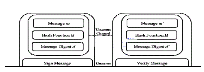
| DSA and RSA both are implemented in existing system EAACK. The performances comparison of DSA and RSA in
MANETs is one of the main purposes. Figure 2 show the general flow of data communication with digital signature. First, a
fixed-length message digest is computed through a pre agreed hash function H for every message m. So that this process
can be described as |
| H (m) = d (1) |
| Second, the sender Alice should apply its own private key Pr−Alice to the computed message digest (d). The result is a
signature SigAlice. It is attached to message m and Alice’s secret private key |
 |
| To verify the validity of the digital signature, the sender Alice always keep her private key Pr−Alice as a secret without
revealing to anyone else. Or else, if the attacker Eve gets this secret private key means, she can intercept the message and
easily add malicious messages with Alice’s signature and send them to Bob. These malicious messages are digitally signed
by Alice and Bob sees them as legit and authentic messages from Alice. Alice can send a message m along with the
signature SigAlice to Bob via an unsecured channel. Then Bob computes the received message m’ against the pre agreed hash
function H to get the message digest d’. This type of process can be generalized as |
 |
| And Bob can verify the signature by applying Alice’s public key Pk−Alice on SigAlice, by using |
 |
| If d == d_, so it is safe to claim that the message m_ transmitted through an unsecured channel is indeed sent from Alice
and the message itself is intact. |
| Figure 3 describes EAACK scheme work process and describes system control flow, and shows the system flow of how
the EAACK scheme works. |
| EAACK is consisted of three major parts.1.ACK, 2.Secure ACK (S-ACK), and 3.Misbehavior Report Authentication
(MRA). |
| B. ACK: |
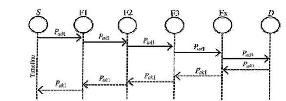
| ACK is an end-to-end acknowledgment scheme. And it acts as one of the part of the hybrid scheme in EAACK. It aims
to reduce network overhead when no network misbehavior is detected. ACK mode in figure8 described, and node S first
sends out an ACK data packet Pad1 to the destination node D. Determine all the intermediate nodes along the route between
nodes S and D are cooperative and node D successfully receives Pad1. The node D is required to send back an ACK
acknowledgment packet Pak1 along the same route but in a reverse order. If node S receives Pak1 within a predefined time
period. Then the packet transmission from node S to node D is successful. Or else, node S will move to S-ACK mode by
sending out an S-ACK data packet to detect the misbehaving nodes in the route. |
| C. S-ACK: |
| TWOACK’s improved level is called as Secure ACKnowledgment. The purpose is every three consecutive nodes work
in a group to detect misbehaving nodes in network. For every three consecutive nodes participate in the route. If the third
node is should send an S-ACK acknowledgment packet to the first node. The purpose of introducing S-ACK mode is to
detect misbehaving nodes in the presence of receiver collision or limited transmission power. Figure. 4 shows S-ACK
mode, and the three consecutive nodes (i.e., F1, F2, and F3) work in a group to detect misbehavior nodes in the network.
First node F1 sends S-ACK data packet Psad1 to node F2. And then, the node F2 forwards this packet to node F3. After
when node F3 receives Psad1 and node F3 is required to send back an S-ACK acknowledgment packet Psak1 to node F2.Then
node F2 forwards Psak1 back to node F1. Otherwise node F1 does not receive this acknowledgment packet within a
predefined time period means, nodes F2 and F3 both are reported as malicious nodes. And also, a misbehavior report will
be generated by node F1 and sent to the source node S. The source node immediately trusts the misbehavior report. But
EAACK requires the source node to switch to MRA mode and confirm this misbehavior report. Moreover it is a vital step
to detect false misbehavior report in our proposed scheme. |
| D. MRA: |
| Misbehavior Report Authentication (MRA) scheme is designed to detect misbehaving nodes with the presence of false
misbehavior report. Then the false misbehavior report can be generated by malicious attackers to falsely report innocent
nodes as malicious. This type of attack can be affecting the entire network when the attackers break down sufficient nodes
and thus cause a network division. The goal of MRA scheme is to authenticate, if the destination node has received the
reported missing packet through a different route. To mention the MRA mode, first the source node searches its local
knowledge base and seeks for an alternative route to the destination node. Otherwise there is no other that exists. |
| Then the source node starts a DSR routing request to find another route. Based on the nature function of MANETs, it is
most common to find out multiple routes between two nodes .To adopting an alternative route to the destination node, we
win the misbehavior reporter node. And when the destination node receives an MRA packet, it should search its local
knowledge base and compares if the reported packet was received. Otherwise it is already received means, it is safe to
decide that this is a false misbehavior report and whoever generated this report is marked as malicious. Or else, the
misbehavior report is trusted and accepted by source node. To the adoption of MRA scheme and EAACK is capable of
detecting malicious nodes despite the existence of false misbehavior report. All three major parts are relying on
acknowledgment packets to detect misbehaviors in the network. It is extremely important to ensure that all
acknowledgment packets in EAACK are authentic one. Or else, if the attackers are smart enough to forge acknowledgment
packets. And all of the three schemes will be vulnerable. |
IV. PROBLEM DEFINITION |
| The existing scheme implemented both DSA and RSA in EAACK scheme. The DSA scheme always produces slightly
less network overhead than RSA does. The signature size of DSA is much smaller than the signature size of RSA. The RO
differences between RSA and DSA schemes vary with different numbers of malicious nodes. The number of malicious
nodes are provides more ROs in the RSA scheme process. More malicious nodes require more acknowledgment packets.
Based on that it increasing the ratio of digital signature in the whole network overhead [2]. Many of the existing IDSs in
MANETs adopt an acknowledgment based scheme, including EAACK. The functions of such detection scheme largely
depend on the acknowledgment packets. Hence, it is guarantee that the acknowledgment packets are valid and authentic by
using digital signature. In this research work, our goal is to propose an IDS specially designed for MANETs, which solves
routing overhead caused by digital signature but also improve the security in system. |
V. PROPOSED SYSTEM |
| In this paper, we propose a hybrid cryptography technique to reduce the network overhead caused by digital signature.
Some times more malicious nodes are present in the network. In more malicious nodes require more acknowledgement
packets. At that time the ratio of digital signature in the whole network overhead. In the presence of malicious nodes,
routing overhead reduced by any hybrid techniques [6]. Our propose a hybrid technique by using RSA and AES. In this
research work, first we find out the secure route for data transmission. The sender sends a data to the destination in
securely. In our work, sender sends a request message for route identification to the destination. Route identification based
on AODV (Ad hoc On-demand Distance Vector routing protocol) protocol concept. The AODV routing protocol is a
reactive routing protocol. Because, routes are determined only when nodes needed. |
| AODV is capable of both unicast and multicast routing. AODV builds routes using a route request / route reply query
cycle. A source node desires a route to a destination for which it does not already have a route; it broadcasts a route request
(RREQ) packet across the network [7]. Nodes receiving this packet update their information for the source node and set up
backwards pointers to the source node in the route tables. |
| In addition to the source node's IP address and current sequence number and broadcast ID, and also the RREQ contains
the most recent sequence number for the destination of which the source node is aware. Then a node receiving the RREQ
may send a route reply (RREP) if it is either the destination or if it has a route to the destination with corresponding
sequence number greater than or equal to that contained in the RREQ. It unicast a RREP back to the source. Or else, it
rebroadcasts the RREQ. Then nodes keep track of the RREQ's source IP address and broadcast ID. But they receive a
RREQ which they have already processed. Then they discard the RREQ and do not forward it. |
| As the RREP propagates back to the source, then nodes set up forward pointers to the destination. Once the source node
receives the RREP means it may begin to forward data packets to the destination. The source receives a RREP containing a
greater sequence number or contains the same sequence number with a smaller hop count. Then it updates its routing information for that destination and begins using the better route. Based on this protocol, the destination is required to send
a reply message to the corresponding sender. |
| After getting a secure route, our send a data securely to the destination by using hybrid encryption techniques. The
source node sent data will be encrypted with RSA and AES before its travelling to the destination node. Before receiving
the data to the destination node will decrypted with RSA and AES. In our work with malicious and non malicious nodes in
the network. At the destination node the data will be available for decryption process. Destination node receives the data.
The destination node required to send an acknowledgement packet to the source. In the presence of malicious node, the
destination node is not received the data from the source. Because the sender node cannot be identified the route to the
destination. |
VI. PERFORMANCE EVALUVATION |
A. Simulation Configuration |
| Our simulation is conducted within the Network Simulator (NS) 2.28 have platform with GCC 4.3 and Fedora 13. A
laptop contains with Core 2 Duo T7250 CPU and 3-GB RAM. To getting better compare our simulation results with other
research works, we adopted to NS 2.28 default scenario settings. The intention is to provide more general results and make
it easier for us to compare the results. In NS 2.28, the default configuration specifies 50 nodes in a flat space with a size of
670 × 670 m. The maximum hops are allowed in this configuration setting are four. |
| Both the physical layer and the 802.11 MAC layer are included in the wireless extension of NS2. The moving speed of
mobile node is limited to 20 m/s and a pause time of 1000 s. User Datagram Protocol traffic with constant bit rate is
implemented with a packet size of 512 B. |
| For each scheme, we ran every network scenario three times and calculated the average performance. |
| B. Routing overhead (RO) |
| Routing Overhead defines the ratio of the amount of routing related transmissions [Route REQuest (RREQ), Route
REPly (RREP), Route ERRor (RERR), ACK, S-ACK, and MRA].During the simulation, the source route makes unicast
and multicast an RREQ message to all the neighbors within its communication range. |
| Upon receiving this RREQ message, each and every neighbor appends their addresses to the message and broadcasts
this new message to their neighbors. In case any node receives the same RREQ message more than once, it ignores it. If
there is a failed node is detected means, it generally indicates a broken link in flat routing protocols like AES, a RERR
message is sent to the source node. The RREQ message arrives to its final destination node, it initiates an RREP message
and sends this message back to the source node by reversing the route in the RREQ message. |
| But theoretically the data is open to two attacks, first one is brute-forcing the RSA and get the secret key to decrypt the
AES and second one is directly by brute-forcing the AES. But again using 2048-bit RSA and 256-bit AES wouldn't be
possible to brute-force any of them any time soon. Such that the 256-bit AES must be harder than the 2048-bit RSA, else
the data is now less secure. But since AES is 'thousands of times' faster than RSA this doesn't feels true. By Guessing a 32-
byte AES password seems easier than guessing the much longer private key. |
| C. Performance Evaluation |
| 1. Scenario 1: |
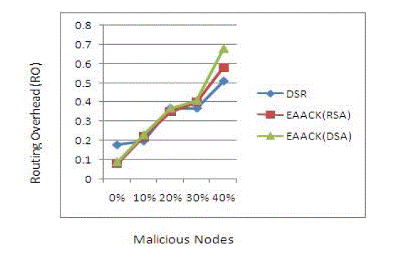
| In Scenario 1 have existing system results. That contain no of malicious nodes and routing over head (RO). In here we
apply RSA and DSA algorithms in DSR routing protocol. |
| results for scenario 2- RO |
| 2. Scenario 2: |
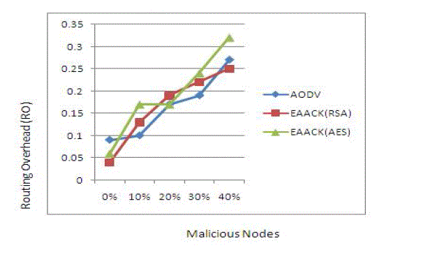
| In Scenario 1 have existing system results. That contain no of malicious nodes and routing over head (RO). In here we
apply RSA and AES algorithms in AODV routing protocol. |
| In figure 6 at initial stage RO level is very low. Then increasing no of malicious nodes the routing overhead level should
be increased |
| Compare to figure 5 and figure 6 the RO level should be decreased in figure 6. Because we use AODV protocol and
public key cryptography based on RSA and AES algorithms. This is our proposed system result. |
VII. CONCLUSION AND FUTURE WORK |
| Packet-dropping attack has always been a major threat to the security in MANETs. Although it generates more ROs in
some cases, we think that this tradeoff is worthwhile when network security is the top priority. Furthermore, in an effort to
prevent the attackers from initiating forged acknowledgment attacks, we extended our research to incorporate hybrid
technique in our proposed scheme; it can reduce the routing overhead in the network. |
| To increase the merits of our research work, we plan to investigate the following issues in our future research: |
| 1) Examine the possibilities of adopting a key exchange mechanism to eliminate the requirement of pre-distributed
keys; |
| 2) Testing the performance of EAACK in real network environment instead of software simulation |
| |
Tables at a glance |
 |
 |
| Table 1 |
Table 2 |
|
| |
Figures at a glance |
 |
 |
 |
| Figure 1 |
Figure 2 |
Figure 3 |
 |
 |
 |
| Figure 4 |
Figure 5 |
Figure 6 |
|
| |
References |
- R. H. Akbani, S. Patel, and D. C. Jinwala, âÃâ¬ÃÅDoS attacks in mobile ad hoc networks: A survey,âÃâ¬Ã in Proc. 2nd Int. Meeting ACCT, Rohtak, Haryana,India, 2012, pp. 535âÃâ¬Ãâ541.
- Y. Hu, A. Perrig, and D. Johnson, âÃâ¬ÃÅARIADNE: A secure on-demand rout-ing protocol for ad hoc networks,âÃâ¬Ã in Proc. 8th ACM Int. Conf. MobiCom,Atlanta, GA, 2002, pp. 12âÃâ¬Ãâ23.
- K. Liu, J. Deng, P. K. Varshney, and K. Balakrishnan, âÃâ¬ÃÅAn acknowledgment-based approach for the detection of routing misbe-haviour inMANETs,âÃâ¬Ã IEEE Trans. Mobile Comput., vol. 6, no. 5, 536âÃâ¬Ãâ550, May 2007.
- A. Patwardhan, J. Parker, A. Joshi, M. Iorga, and T. Karygiannis, âÃâ¬ÃÅSecure routing and intrusion detection in ad hoc networks,âÃâ¬Ã in Proc. 3rd Int.Conf. Pervasive Comput. Commun., 2005, pp. 191âÃâ¬Ãâ199.
- A. Singh, M. Maheshwari, and N. Kumar, âÃâ¬ÃÅSecurity and trust management in MANET,âÃâ¬Ã in Communications in Computer and Information Science,vol. 147. New York: Springer-Verlag, 2011, pt. 3, pp. 384âÃâ¬Ãâ387.
- S. Marti, T. J. Giuli, K. Lai, and M. Baker, âÃâ¬ÃÅMitigating routing misbe-haviour in mobile ad hoc networks,âÃâ¬Ã in Proc. 6th Annu. Int. Conf. MobileComput. Netw., Boston, MA, 2000, pp. 255âÃâ¬Ãâ265.
- J.-S. Lee, âÃâ¬ÃÅA Petri net design of command filters for semiautonomous mobile sensor networks,âÃâ¬Ã IEEE Trans. Ind. Electron., vol. 55, no. 4,1835âÃâ¬Ãâ1841, Apr. 2008.
- N. Nasser and Y. Chen, âÃâ¬ÃÅEnhanced intrusion detection systems for dis-covering malicious nodes in mobile ad hoc network,âÃâ¬Ã in Proc. IEEE Int. Conf.Commun., Glasgow, Scotland, Jun. 24âÃâ¬Ãâ28, 2007, pp. 1154âÃâ¬Ãâ1159.
- T. Sheltami, A. Al-Roubaiey, E. Shakshuki, and A. Mahmoud, âÃâ¬ÃÅVideo transmission enhancement in presence of misbehaving nodes in MANETs,âÃâ¬ÃÂInt. J. Multimedia Syst., vol. 15, no. 5, pp. 273âÃâ¬Ãâ282, Oct. 2009.
- M. Zapata and N. Asokan, âÃâ¬ÃÅSecuring ad hoc routingprotocols,âÃâ¬Ã in Proc. ACM Workshop Wireless Secur., 2002, pp. 1âÃâ¬Ãâ10.
- D. Johnson and D. Maltz, âÃâ¬ÃÅDynamic Source Routing in ad hoc wireless networks,âÃâ¬Ã in Mobile Computing. Norwell, MA: Kluwer, 1996, ch. 5,153âÃâ¬Ãâ181.
- K. Liu, J. Deng, P. K. Varshney, and K. Balakrishnan,âÃâ¬ÃÅAn acknowledgment-based approach for the detection of routing misbe-haviour inMANETs,âÃâ¬Ã IEEE Trans.MobileComput., vol. 6, no. 5,536âÃâ¬Ãâ550, May 2007.
|