Keywords
|
| Distributed Generation System (DGS), Droop Method, Virtual Impedance Concepts, Hierarchical Control, Microgrid (MG), Voltage Source Inverters (VSIs). |
INTRODUCTION
|
| Newly, curiosity in Microgrids (MGs) is hastily escalating, predominantly in small scale industries. New-fangled power electronic equipment will govern the electrical grid in the next decades. Consistently Voltage Source Inverters (VSIs) are worn as interface of power electronics; consequently, the formation of MG by controlling the parallel VSIs has been investigated in recent years [1]–[9]. The hierarchical control systems are inevitable, which are capable to contrive both in grid connected and in island mode, with the enhancement of power electronic based MGs. The virtual impedance loop have been urbanized, in order to augment the consistency and performances of the droop controlled VSIs, providing to the inverters with hot swap operation, harmonic power sharing, etc [10]. The focal predicament to be solved in such works is the frequency control of the system. Nevertheless, voltage stability and synchronization issues are additionally imperative to accomplish adequate suppleness to maneuver in both modes. |
| Microgrid power systems are small scale power generation solutions built around local power generating facilities and individual homes and buildings equipped with renewable power systems.They address the vulnerabilities of the national system as follows: Microgrids are cheaper in cost. They use renewable resources so are more environmentally friendly with lower carbon footprints. They require fewer technical skills to operate and rely more on automation. They are isolated from any grid disturbance or outage. They place the consumer in more control. They are national defense positive. Attacks on one part of the system will not destroy the whole system. It is healthier for our economy to eat local. It is healthier to generate power locally. |
| For instance, the predictable droop method is not apposite when the paralleled system must contribute to nonlinear loads because the control units should take into account harmonic currents as well as to balance active and reactive power. Thus, harmonic current sharing techniques have been proposed to avoid the circulating deformation power when sharing nonlinear loads. In order to employ such a category of multilevel control algorithm, it is obligatory to concern for communication systems to propel information among the DG units [17]–[20]. Some implications were made by combination of low-bandwidth communications with average power sharing, droop control and extra harmonic compensation control loops in order to perk up the negative aspects of droop controlled VSIs[18], [19]. |
| In the case of shifting from islanded operation to grid connected mode, it is crucial to first synchronize the MG to the grid. Thus, a distributed synchronization control algorithm is indispensable [1]. On one occasion the synchronization is accomplished, a static transfer switch attaches the MG to the grid or to an MG cluster. Later than the transfer process between islanded and grid-connected modes is refined, it is obligatory to control the active and reactive power flows at the point of common coupling. |
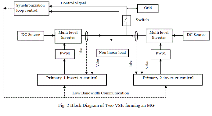
| Two sets of inverters are worned in order to provide the uninterrupted supply to the load. Among the various types of inverters used, diode clamped inverters are preferable since it is probable to afford the multiple voltage level and diminish the stress on other electrical devices.The multi-level inverter is to synthesize a near sinusoidal voltage from numerous levels of dc voltages. As number of levels increases, the synthesized output waveform has more steps, which provides a staircase wave that approaches a desired waveform. Also, as steps are added to waveform, the harmonic distortion of the output wave decreases, approaching zero as the number of voltage levels increases. |
| The main concept of this inverter is to use diodes and provides the multiple voltage levels through the different phases to the capacitor banks which are in series. A diode transfers a limited amount of voltage, thereby reducing the stress on other electrical devices. The maximum output voltage is half of the input DC voltage. It is the main drawback of the diode clamped multilevel inverter. This problem can be solved by increasing the switches, diodes and capacitors. Due to the capacitor balancing issues, these are limited to the three levels. This type of inverters provides the high efficiency because the fundamental frequency used for all the switching devices and it is a simple method of the back to back power transfer systems.Benefit over this system is if one inverter trips, another can capable to deliver the load, the system will still remain stable [21]. These all specifics emphasize the consistency and the excellent performance of the MG control system. |
| This paper is prearranged as follows. In Section II, illustrate the primary control. Section III suggests a coordinated synchronization control loop for the MG. Section IV presents the secondary control for frequency and voltage amplitude restoration. Section V clarifies the simulation results. Finally, Section VI depicts the conclusion of this paper. |
PRIMARY CONTROL
|
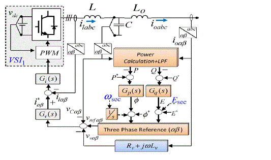
| To regulate the frequency and amplitude of the voltage reference endow with the inner current and voltage control loops, primary control level is employed. Using the renowned P/Q droop method the above theory can be incorporated in VSIs as pursues. |
 |
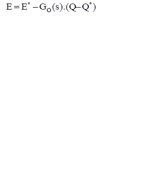 |
| Where ω and E specifies the output voltage reference of the frequency and amplitude, ω* and E* corresponds to their references, P and Q are the active and reactive power, P* and Q* are their references, and GP(S) and GQ(S) are their consequent transfer functions. |
A. Droop Control and Virtual Impedance Loop
|
| For paralleled inverters, to imitate virtual inertias the droop method composed of subtracting relative parts of the output standard active and reactive powers from the frequency and amplitude of each section. While obtaining good power sharing, these control modules have been applied for parallel connection of inverters with UPS systems to evade mutual control wires [4]. |
| With the subsequent correlation [16], this method composed of a power block computation that computes P and Q in the αβ-coordinates as, |
 |
 |
| Virtual impedance control algorithms have been built-up, provided that to the inverters with hot-swap operation, harmonic power sharing and toughness for large line power impedance variations [10], in order to improve the consistency and performances of the droop controlled VSIs. |
 |
 |
| Where Lv and Rv specifies the virtual inductance and resistance value and ioα,β and Vvα,β specifies the output current and voltage in the αβ frame correspondingly. The block diagram of two VSIs forming an MG is shown in fig 2. |
COORDINATED SYNCHRONIZATION LOOP
|
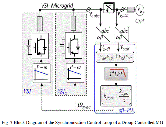
| The synchronization algorithm allows the synchronization of the renewable agent with the utility grid for grid connected power system to deduct the computational requirement. For synchronizing all the VSI of the MG, a coordinated synchronization loop is indispensable. Using the αβ components of the grid and the VSI voltage variables Vgαβ and Vcαβ synchronization loop is implemented as shown in fig 3. After the synchronization of both voltages, presume that |
 |
| Where x represents the average value of the variable x with the grid frequency.Thus, the above affiliation can be derived using the subsequent PLL structure, which is composed of this orthogonal product, a low-pass filter and a PI controller |
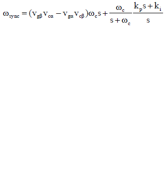 |
| Where kp and ki be the coefficients of the PI and ω be the output of the synchronized PLL to be sent to both VSI to regulate their each droop function, integrating and adding in excess with the phase of the system, as it can be seen in fig 1 and 3. |
SECONDARY CONTROL
|
| In order to reimburse for the frequency and amplitude deviations as well as for eradicate any steady state error pioneered by the primary control [15], [16], a secondary control is projected. By enchanting the grid constraint [22], the secondary control be supposed to exact the frequency deviation contained by the tolerable limit. |
A. Frequency Restoration
|
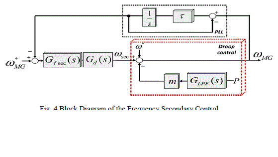
| To investigate the system stability as well as to regulate the parameters of the frequency secondary control, a model has been proposed as shown in fig 4. Other proposals use communications between an MG central controller and each DG local controller. The methodology proposed in [20] and [22] is persistent on with the aforesaid secondary control to renovate the frequency deviation shaped by the local active power/frequency droop characteristic. |
| It allocates for regulating the control parameters of the secondary control as well as to cram the inadequacy of the communication delay. It comprises the droop control of the system, the simplified PLL first order transfer function used to extort the frequency of the MG and the secondary control Gf sec(s), pursued by a delay Gd sec(s) for the communication lines. |
B. Amplitude Restoration
|
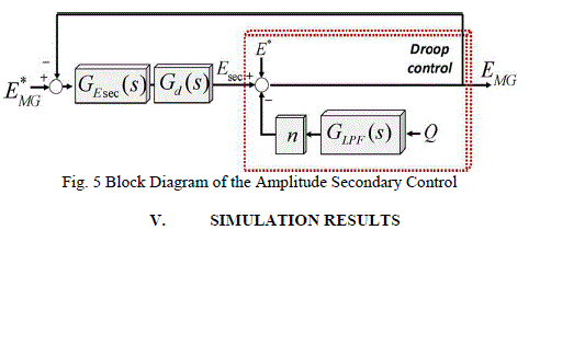
| Analogous process has been applied for designing the voltage secondary controller as well as for obtaining the closed loop voltage dynamic model. The block diagram of the amplitude secondary control is shown in fig 5. To renovate the deviations twisted by the primary control, this control will be implemented using an external centralized controller. |
SIMULATION RESULTS
|
| Some simulation results from a 3Ãâ°Ã¸ inverter MG are obtainable. If the generated power is in surplus with the nonlinear load, it should be afforded to the main grid or else there is a scarcity of generated power to the load, it should be acquired from the main grid. In secondary control, the grid voltage and the frequency can be compared using low bandwidth communication with the primary control. If there is any deviation, the inverters values are altered with grid values. The selected control parameters are listed in Table 1. |
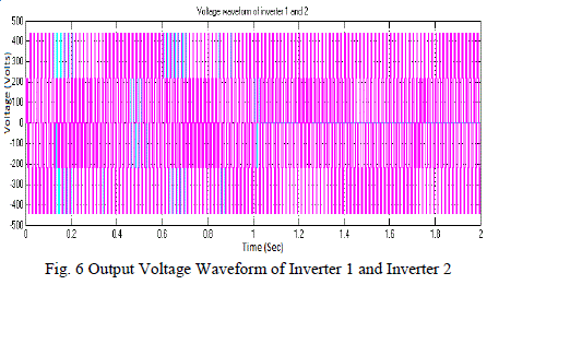
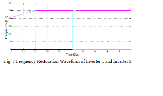
| At initial, both inverters were coupled and provided supply to the nonlinear load. The output voltage of both inverters is 440V. Afterward, at t=1.2s, some interruption occurs in inverter 1, it gets detached from the MG, i.e., it gets turned off; its voltage value is 0V. The inverter 2 is supplying all the required power i.e., the output voltage of inverter 2 is 440V. The output voltage for inverter 1 and 2 are shown in fig 6, with blue and pink colour specifies the output voltage of inverter 1 and 2 correspondingly. At t=0.16s, the voltage (amplitude) gets unbalanced and it regains to normal amplitude after 200ms. |
| The frequency and amplitude renovation action done by the secondary control are shown in fig 6 and 7 respectively. At preliminary, the frequency gets deviated and it is restored after 400ms. After t=1s the inverter 1 gets turned off, its frequency accomplishes 0 Hz and the frequency of inverter 2 sustained in the similar value. |
CONCLUSION
|
| This paper proposes the hierarchical control for three phase paralleled VSI based MGs. This control configuration was ordered of two control levels. The primary control composed of the droop control method and the virtual impedance concepts. Pursued by this, the confined centralized controller known as the secondary control is responsible for power sharing with the intention of renovating the frequency and amplitude deviations twisted by the above control methods. The different levels of control have been replicated and the closed loop system dynamics has been investigated. Simulation results have revealed the excellent concert and augment the consistency of the MG control system. |
Tables at a glance
|
 |
| Table 1 |
|
Figures at a glance
|
 |
 |
 |
 |
| Figure 1 |
Figure 2 |
Figure 3 |
Figure 4 |
 |
 |
 |
| Figure 5 |
Figure 6 |
Figure 7 |
|
References
|
- J. C. Vasquez, J. M. Guerrero, J. Miret, M. Castilla and L. G. de Vicuna, âÃâ¬Ãâ¢Hierarchical control of intelligent microgrids,âÃâ¬Ãâ IEEE Ind. Electron.Mag., vol. 4, no. 4, pp. 23–29, Dec. 2010.
- T. C. Green and M. Prodanovic, âÃâ¬Ãâ¢Control of inverter-based micro-grids,âÃâ¬Ãâ Elect. Power Syst. Res., vol. 77, no. 9, pp. 1204–1213, Jul. 2007.
- N. Pogaku, M. Prodanovic and T. C. Green, âÃâ¬Ãâ¢Modeling, analysis and testing of autonomous operation of an inverter-based Micro Grid,âÃâ¬ÃâIEEETrans. Power Electron., vol. 22, no. 2, pp. 613–625, Mar. 2007.
- R. Teodorescu, F. Blaabjerg, M. Liserre and P. C. Loh, âÃâ¬Ãâ¢Proportional–resonant controllers and filters for grid-connected voltage sourceconverters,âÃâ¬Ãâ Proc. Inst. Elect. Eng. Elect. Power Appl., vol. 153, no. 5, pp. 750–762, Sep. 2006.
- M. B. Delghavi and A. Yazdani, âÃâ¬Ãâ¢An adaptive feedforward compensation for stability enhancement in droop-controlled inverter-basedmicrogrids,âÃâ¬Ãâ IEEE Trans. Power Del., vol. 26, no. 3, pp. 1764–1773, Jul. 2011.
- C. K. Sao and P. W. Lehn, âÃâ¬Ãâ¢Control and power management of converter fed microgrids,âÃâ¬Ãâ IEEE Trans. Power Syst., vol. 23, no. 3, pp. 1088–1098, Aug. 2008.
- E. Barklund, N. Pogaku, M. Prodanovic, C. Hernandez Aramburo and T. C. Green, âÃâ¬Ãâ¢Energy management in autonomous microgridusingstability-constrained droop control of inverters,âÃâ¬Ãâ IEEE Trans. Power Electron., vol. 23, no. 5, pp. 2346–2352, Sep. 2008.
- R. Majumder, A. Ghosh, G. Ledwich and F. Zare, âÃâ¬Ãâ¢Angle droop versus frequency droop in a voltage source converter based autonomousmicrogrid,âÃâ¬Ãâ in Proc. PES, 2009, pp. 1–8.
- F. Katiraei and M. R. Iravani, âÃâ¬Ãâ¢Power management strategies for a microgrid with multiple distributed generation units,âÃâ¬Ãâ IEEE Trans. PowerSyst., vol. 21, no. 4, pp. 1821–1831, Nov. 2006.
- J. M. Guerrero, J. C. Vasquez, J. Matas, M. Castilla and L. G. de Vicuna, âÃâ¬Ãâ¢Control strategy for flexible microgrid based on parallel lineinteractiveUPS systems,âÃâ¬Ãâ IEEE Trans. Ind. Electron., vol. 56, no. 3, pp. 726–736, Mar. 2009.
- P. L. Villeneuve, âÃâ¬Ãâ¢Concerns generated by islanding,âÃâ¬Ãâ IEEE Power Energy Mag., vol. 2, no. 3, pp. 49–53, May/Jun. 2004.
- M. C. Chandorkar, D. M. Divan and R. Adapa, âÃâ¬Ãâ¢Control of parallel connected inverters in standalone AC supply systems,âÃâ¬Ãâ IEEE Trans. Ind.Appl., vol. 29, no. 1, pp. 136–143, Jan./Feb. 1993.
- J. M. Guerrero, J. C. Vasquez, J. Matas, L. Garcia de Vicuna and M. Castilla, âÃâ¬Ãâ¢Hierarchical control of droop-controlled AC and DCmicrogrids—A general approach towards standardization,âÃâ¬Ãâ IEEE Trans. Ind. Electron., vol. 58, no. 1, pp. 158–172, Jan. 2011.
- J. He and Y. Lee, âÃâ¬Ãâ¢Analysis and design of interfacing inverter output virtual impedance in a low voltage microgrid,âÃâ¬Ãâ in Proc. IEEE ECCEConf., 2002, pp. 2857–2864.
- H. Matthias and S. Helmut, âÃâ¬Ãâ¢Control of a three phase inverter feeding an unbalanced load and operating in parallel with other power sources, in Proc. EPE-PEMC Conf., 2002, pp. 1–10.
- E. Hoff and T. Skjellnes, âÃâ¬Ãâ¢Paralleled three-phase inverters,âÃâ¬Ãâ in Proc. NORPIE Conf., 2004, pp. 1–6.
- A.Hasanzadeh, O. C. Onar, H. Mokhtari and A. Khaligh, âÃâ¬Ãâ¢A proportional–resonant controller-based wireless control strategy with a reducednumber of sensors for parallel-operated UPSs,âÃâ¬Ãâ IEEE Trans. Power Del., vol. 25, no. 1, pp. 468–478, Jan. 2010.
- M. N. Marwali and A. Keyhani, âÃâ¬Ãâ¢Control of distributed generation systems—Part I: Voltages and currents control,âÃâ¬Ãâ IEEE Trans. PowerElectron., vol. 19, no. 6, pp. 1541–1550, Nov. 2004.
- M. N. Marwali, J. Jin-Woo and A. Keyhani, âÃâ¬Ãâ¢Control of distributed generation systems—Part II: Load sharing control,âÃâ¬Ãâ IEEE Trans. PowerElectron., vol. 19, no. 6, pp. 1551–1561, Nov. 2004.
- J. A. P. Lopes, C. L. Moreira and A. G. Madureira, âÃâ¬Ãâ¢Defining control strategies for microgrids islanded operation,âÃâ¬Ãâ IEEE Trans. Power Syst.,vol. 21, no. 2, pp. 916–924, May 2006.
- M. B. Delghavi and A. Yazdani, âÃâ¬Ãâ¢Islanded-mode control of electronically coupled distributed-resource units under unbalanced and nonlinearload conditions,âÃâ¬Ãâ IEEE Trans. Power Del., vol. 26, no. 2, pp. 661–673, Apr. 2011.
- UCTE, Technical Paper—Definition of a Set of Requirements to Generating Units, 2008.
|