Keywords
|
| Chloroform, Ethanol, Gravity, Methanol, Microchannel, Microfluidic. |
INTRODUCTION
|
| The miniaturization and integration of microfluidic components has been exploited tremendously resulting into development of various microfluidic devices integrated using different fabrication methods [1]. Microfluidics is at present in its adolescence that seems promising technology to be practically used in various applications in spite of its limitations. It offers solutions to non-expert users working in nanolithography or fluid physics to explore applications in fluidic optics and organic synthesis of cells in micro channels [2]-[5]. |
| Recent investigations have shown microfluidics as an emerging technique for microanalysis of fluids for biomedical research [5] and other micro scale applications such as bio-medicines [6], [7], chemical bindings, immunoassays, cell sorting, and cell separations [2]. It is also used in measurement applications such as fluid viscosity, cytometric analysis of cells [8], capillary electrophoresis [1], [9], diffusion coefficients [10], etc. DNA sequencing and its purification is one of the important microfluidic applications in biomedical research. Microfluidic device may be distinguished from other devices by a fact that they contain either one or more channel of small dimensions nearly less than 1 mm [1], [2]. Microfluids include common fluids such as bacterial cell suspensions, blood samples, proteins or antibody solutions, etc. [1], [2]. Literature review of microfluidics shows its usefulness in various microscale applications [6], [11] - [16]. |
| Zingerle and Richter in the year 1994 reported the dynamic behavior of microfluidic devices such as micro valves, diaphragm pumps, and flow channels providing an alternate way to study the dynamic behavior of complex fluid systems. Stone et.al [11] in the year 2003 presented a review paper discussing an overview of flows in microfluidic devices focusing on electro kinetics, mixing, dispersion, and multiphase flows thereby illustrating the industrial and scientific usage of microfluidics. Various dynamical problems associated with fluids due to multiple physical effects such as pressure gradients, capillarity electro kinetics, etc. were also discussed. Zhang et. al [12] in the year 2008 concluded that most of the micro fabrication processes are planar based techniques. The topological effects of electrodes on electric field distribution were studied in simulation using the COMSOL 4.2. Barbaros et.al [13] in the year 2009 investigated the separation of particles and cells using ACDEP. Nag et.al [14] in the year 2010 reviewed the developments in the microfluidics based immunoassays since 2000 and observed it as a promising technique with the miniaturization in microfluid system as a great advantage in immunoassays. An alternate way to previously used microfluidic manipulation techniques such as electro kinetic flow has been developed for complex biological analysis and called digital microfluidics. Li et. al [6] in year 2012 reported a cost efficient novel method to construct 3D microelectrodes in the field of microfluidics using the photolithography and sputtering techniques. Jay Raj et.al [14] in the year 2010 reviewed the mixing in microfluids summing up different investigations in microfluidics since 2005 on the analysis of fluid flow and mixing in micro-channels further providing an experimental technique to measure flow pattern, velocity, and mixing performance of micro mixers enlightening the importance of micro mixing in biochemical analysis using lab on chip microfluidic terminology. Different designs of micro mixers were described and a focus on mixing performance of each has been made. Wong et.al [15] in the year 2012 worked for sorting and then separating micro dimension particles continuously with respect to size using a PDMS based ACDEP device. Murray et al. [16] in year 2012 described the microfluidic tuning of channels using polymer actuators exploring the application of microfluidics in the biology and medicinal field to accomplish the on chip fluid sample manipulation and development of EAM. |
| The parameters of the flow of microfluids in a channel may depend upon the shape, size, material, and orientation of the channel. It may be expected that elevated orientations may also affect the flow rate of the fluid in the given microchannel due to gravity. The objective of this paper is to investigate the effect of gravity on microfluidic flow. The basics of microfluidics are presented in Section II as follows. The methodology of the investigations is illustrated in Section III. The results and discussions are presented in Section IV, followed by Conclusion in Section V. |
MICROFLUIDIC BASICS
|
| The numerical modeling of microfluidics is an optimization tool used to visualize the complex flow phenomenon which otherwise is difficult to obtain experimentally [1]. Some microfluidic analysis parameters are explained in the following sub sections. |
| A. Reynolds Number |
| A dimension less parameter known as Reynolds number is used to determine the type of flow depending on peculiar flow geometry. Reynolds number is used to characterize the flow of the fluid through a micro channel and is defined mathematically as [1]: |
 |
| where L= 4A/P is the channel length, A the crossectional area of the channel, P the wetted perimeter of the channel, μ the viscosity, ρ the fluid density, and Vavg the average velocity of flow [1]. |
| Re depends on material properties (density, viscosity), boundary conditions, and critical velocity. Reynolds number less than 25 is common in microfluidics. On basis of Reynolds number and the channel cross section geometry, the variation in critical transition point of fluid flow is determined to be either laminar, transient, or turbulent flow as tabulated below [17]. |
| Since microchannels are small in dimensions, Reynolds number Re is much less than 100 and often less than 1 in microfluidics which means the flow of microfluids is laminar without occurrence of any turbulence. Further, this laminar flow of micro fluid can also transit to the turbulent flow if the Reynolds number acquires range of about 2000 [18]. |
| B. Types of Flow |
| The fluid flow can be classified into following main types [17]-[20]. The distinguishing characteristic of each type of flow is briefed as: |
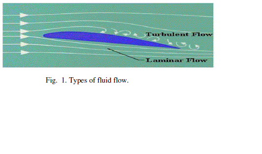
| 1) Laminar flow: This type of fluid flow is a streamline flow in which smooth sliding of adjacent layers that resembles a parallel layer flow has been observed and the field of velocity vectors is constant with time. The flow velocities are relatively low and the Reynolds number value of such fluid flow is less than 2300 [17], [19]. |
| 2) Turbulent flow: The laminar flow at higher velocities is referred as turbulent flow some times. The Reynolds number value for such flow is usually above 4000. In turbulent type of fluid flow the curling of field lines has been observed which lead to mixing of adjacent layers in such a way that there occurs unpredictable development of the velocity vector field. The flow pattern is observed to be increasingly turbulent towards the higher velocities [17- 20]. |
| 3) Transient flow: It is a periodic flow and termed as third flow regime in micro fluidics. It includes the surface waves and the acoustic waves. The Reynolds number value varies between the 2300 and 4000. |
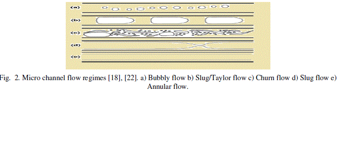
| The microfluidic flow is generally a laminar type of fluid flow identified by the Reynolds number values less than 2300 [18]-[20]. However the fluid flow transition from laminar to turbulent can also occur due to its sensitivity to flow disturbances and channel imperfections. The extreme case of laminar flow is the stokes flow which involves the creeping motion of fluid through channels at Reynolds number lesser than 1. This is due to greater effects of viscous forces acting relative to the inertial forces at low Reynolds number values. The microfluidic flow regime includes various types of flow such as a bubbly flow, slug /Taylor flow, churn flow, slug flow and annular flow [18]-[22]. These flows are shown in Fig. 2. |
| C. Viscosity |
| Viscosity of a fluid is defined as its internal resistance to its flow. The property of posing a friction to the fluid flow is termed as the viscosity. It is necessary to determine the flow speed since the fluids with low viscosity are faster flowing when compared to highly viscous fluids [6]. |
| D. Height of Liquid |
| The amount of material drawn due to the capillary action is termed as height of liquid and is denoted by h. Capillary action forms the basis of microfluidics since capillary pressure of a fluid flowing across a microchannel depends on capillary action in which the adhesive intermolecular forces at liquid – substrate interface become more stronger than the cohesive intermolecular forces inside the liquid. Thus whenever fluid interacts with the microchannel i.e. capillary interface, the surface tension induced causes the fluid flow advancing across the microchannel [23]. Human eyes are best example defining capillary action of eyes due to which a tear in eyes gets cleared on every blink of eye. Other examples include absorbent paper towel, candle wicks, etc. [23]. Mathematically, height of liquid is expressed as |
 |
| where γ represents surface tension of fluid, θ is contact angle, r is column radius, g denotes the gravitational force, and ρ is the density [24]. |
| Fluid flow in capillaries of crossectional dimensions above 1mm forms a new fluidic system called milli-fluidic system. In milli fluidic system the transition to turbulence when Reynolds number value reaches 1, can never be neglected. This is a limitation of milli- fluidic system if compared to other fluidic systems or even microfluidic systems [23]. |
METHODOLOGY
|
| The methodology used for proposed investigatings is divided into three steps: microchannel pattern transfer, pattern etching, and temporal fluid flow analysis. These steps are explained as follows. |
| Step1: Microchannel Pattern Transfer |
| A microfluidic channel pattern is fabricated on Cu by screen printing. The shape of the channels for these investigations was chosen as ‘Y’ shaped. The width of the channels was fixed as 1 mm and length as 3.6 cm. The material of the base of the channel was taken as Mica and boundaries as Cu. |
| Step 2: Pattern Etching |
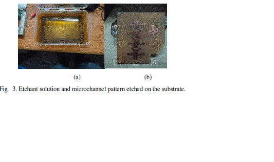
| In etching, unwanted Cu is removed from the substrate using ferric chloride. The etchant solution is prepared using ferric chloride powder and water in the ratio 1:3 by volume (Fig. 3a). The mixture is stirred continuously using a glass rod until whole lump of ferric chloride gets dissolved in the water. The microchannel patterned Cu substrate is dipped in the etchant tray and tray is tilted and moved gently in horizontal and then vertical direction agitating the solution till etching is observed to occur i.e. removal of copper from the mica starts to occur from unexposed areas. To enhance the rate of the reaction, an IR lamp is used to heat the solution. The process takes about 12-15 minutes for completion. The etched pattern is shown in Fig. 3b. |
| Step 3: Temporal Fluid Flow Analysis |
| Investigations were carried out using three fluids –Ethanol, Methanol, and Chloroform. The physical characteristics of these fluids are listed in Table II. |
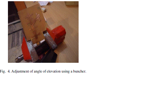
| Metal syringes were used to inject ethanol, methanol, and chloroform in the channel. The flow of the liquid across Cu-Mica microchannel is observed and recorded using a digital movie camera. Investigations were carried out by taking different angles of elevation ranging from 100 to 900 (Fig. 4). |
RESULTS AND DISCUSSIONS
|
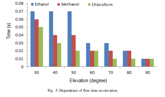
| The results of the investigations are plotted in Fig. 5 and Fig. 6. The flow time for different angles of elevations (Fig. 5) shows that Chloroform requires minimum time and Ethanol takes maximum time at each angle of elevation. At higher angles of elevation, the effect of gravity on flow of different liquids is negligible. |
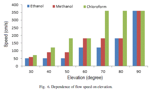
| The speed of flow increases with the angle of elevation (Fig. 6). Chloroform shows maximum speed and Ethanol as minimum at all angles of elevations. The maximum changes in speed (acceleration) shown by Chloroform is in the range 600-700. The maximum acceleration for Methanol and Ethanol is in the same range of 800-900. As the pattern of flow is unique for different liquids, the microchannel analysis may be used for their automatic identification. |
CONCLUSION
|
| The investigations were carried out to study the effect of gravity on the flow of liquids through Cu-Mica microchannels. The analysis of the results showed that different liquids exhibit unique flow patterns and hence they may be identified automatically using microchannel analysis. |
Tables at a glance
|
 |
 |
| Table 1 |
Table 2 |
|
Figures at a glance
|
 |
 |
 |
| Figure 1 |
Figure 2 |
Figure 3 |
 |
 |
 |
| Figure 4 |
Figure 5 |
Figure 6 |
|
References
|
- Radenovic ,“Advanced Bioengineering Methods Laboratory Microfluidics Lab on Chip,” http://tutorial6.com/microfluidics-lab-on-chip-e4141.
- Ashton, R., Padala, C. & Kane, R. S; “Microfluidic Separation of DNA,” in Current Opinion in Biotechnology vol.14, pp. 497-504, 2003.
- http://en.wikipedia.org/wiki/Microfluidics#Digital_.28droplet-based.29_microfluidics.
- P. Ferraro, L. Miccio, S. Grilli, A. Finizio, S. De Nicola, and V. Vespini, "Manipulating Thin Liquid Films for TunableMicrolens Arrays," in Optics &Photonics News , vol. 19, pp. 34-34, 2008.
- http://www.elveflow.com/microfluidic-reviews-and-tutorials/microfluidics-and-microfluidic-devices-a-review.
- Shunbo Li, Ming Li, Yu SannaHui, WenbinCao, Weihua Li, Weijia Wen; “A Novel Method to construct 3D electrodes at the Sidewall of Microfluidic Channel” in MicrofluidNanofluid: Springer, 2012.
- J, Gray ML, Schmidt MA.; “Microfabrication in Biology and Medicine,” Ann. Rev. Biomed. Engg. ; vol. 1(1); pp. 401–425; 1999.
- 8 Huh, D., Gu, W., Kamotani, Y., Grotberg, J. B.&Takayama, S, “Microfluidics for flow Cytometric Analysis of Cells and Particles,” in PhysiolMeas, vol.26, pp. 73-98, 2005.
- Hardt, Steffen; Schönfeld, Friedhelm, “Microfluidic Technologies for Miniaturized Analysis Systems,” in Springer, vol. XXI, pp.393-438, 2007.
- Hatch, A., Garcia, E., Yager, P, “Diffusion-Based Analysis of Molecular Interactions in Microfluidic Devices,” Proceedings of the IEEE, vol. 92(1): pp. 126-139, 2004.
- H.A. Stone, A.D. Stroock, and A. Ajdari, “Engineering Flows in Small Devices: Microfluidics toward a Lab-on-a-Chip.” in Annu. Rev. Fluid Mech. 2004. 36:381–411 doi: 10.1146/annurev.fluid.36.050802.122124, 2003
- Y. T. Zhang, et.al; “Titanium-based Dielectrophoresis Devices for Microfluidic Applications,” 2008
- Barbaros C, “Microfluidic Continuous Separation of Particles and Cells by Ac-Dielectrophoresis,” in Dissertation, 2009
- Alphonsus H. C. Nag & UV-arajUddayasankar& Aaron R. Wheeler, “Immunoassays in Microfluidic Systems,” in Anal BioanalChem (2010) 397:991–1007 doi 10.1007/s00216-010-3678-8, 2010
- NuttawutLewpiriya Wong and Chun Yang, “AC-Dielectrophoretic Characterization and Separation of Submicron and Micron Particles using sidewall Ag PDMS Electrodes,” in Bio-microfluidics. 2012 Mar; 6(1):12807-128079. doi: 10.1063/1.3682049, 2012
- Coleman Murray , David McCoul , et.al, “Electro-adaptive Microfluidics for active tuning of Channel geometry using Polymer actuators,” in MicrofluidNanofluiddoi 10.1007/s10404-012-1055, 2012
- http://en.wikipedia.org/wiki/Nanofluidics
- Nguyen, N.-T.; Wu, Z, “Micromixers, a Review,” in J. Micromech. Micro-eng. 2005, 15, R1-R16 , 2005.
- Jens Ducrée, “Microfluidics in Physics: Laminar and Turbulent Flow,”.www.dcu.ie/~ducreeje/myfluidix/Materials/03_Physics_02.pdf
- Jay raj, S.; Kang, S.; Suh, Y.K , “A review on the analysis and experiment of fluid flow and mixing in micro-channels,” in J. Mech. Sci. Technol., vol. 2, pp 536-548, 2007
- Gennes, Pierre-Gilles de; Francoise Brochard-Wyart, David Quere (2004); “Capillarity and Wetting Phenomena,” in Springer, vol. XV, pp 291, 2004
- Kreutzer MT, Kapteijn F, Moulijn JA, Heisz wolf, “Multiphase Monolithic Reactors: Chemical Reaction Engineering of segmented Flow inMicrochannels,” in JJ ChemEngSci; vol. 22; pp. 5895–5916, 2005.
- Geunther and Michiel T. Kreutzer , “Fluid Dynamics in Microchannels, Multiphase Flow,” in Axel Micro Process Engineering: Fundamentals, Operations and Catalysts, vol. 1, 2009.
- Schuyler Vowell, “Microfluidics: Effects of Surface Tension,” Physics 486 March 12, 2009.
|