This paper describes the modeling and simulation of renewable energy sources based hybrid power system. To meet the load demands different renewable energy sources with local converters are considered to boost up as well as to maintain the output voltage constant. The proposed paper focuses on the combination of photo voltaic (PV), wind turbine system, fuel cell and battery for the power generation. To improve power quality, a DC motor- Synchronous generator set is proposed instead of using the conventional inverter. In order to maintain the power quality as high as possible it is required to have constant system frequency and voltage. This can be achieved by controlling the speed of dc motor-generator set by using the PID controller. Power quality issues are investigated by simulating the hybrid power system with motor-generator set and the results are compared with the existing inverter model to prove the effectiveness of the proposed one .An energy management and control unit(EMCU) is also proposed in our present work. This unit is built on an algorithm which enables the effective utilization of the power from the renewable energy sources and reduces the consumption of electricity from the commercial sources. Modeling and simulation is done using the MATLAB/Simulink.
Keywords |
| Hybrid Power system, Motor-Synchronous generator, power quality, Boost converter, Inverter, Energy
management and control unit. |
INTRODUCTION |
| There are number of motives to build integrated renewable energy based HPS including environmental, economical and
social benefits. Most of these HPS topologies use inverters to interface the renewable sources to the buildings with an
offering of low quality power. The power quality problem is defined as any problem manifested in voltage, current or
frequency deviations that result in malfunctioning of building equipment. This paper proposes the topology of HPS
with dc motor-synchronous generator set instead of inverter in order to improve the power quality. In the present work
along with the power quality issues which are associated with the power system, we are also concentrating on the
energy management between the various renewable energy resources and the load demands. |
| Energy management and control unit is included in our project work. The unit controls the flow of generated power as
per the demands on the load side. An algorithm is built for the energy management which controls the operation of the
circuit breakers. The circuit breakers are placed on both renewable energy source side and the utility side. The EMCU
continuously checks the generation of power from renewable energy side, load demands and also at the utility side. |
LITERATURE SURVEY |
| Electrical energy plays a vital role in today’s trend. In this century as people aim to lead higher quality of life, the
demand for it is more in all the sectors. Unfortunately, still one third of the world’s population fails to access the
electricity [1]. Combining the various types of renewable energy sources will give rise to hybrid power system [2]. |
| The present work focuses on the combination of photo voltaic (PV) cell system, wind turbine system, fuel cell and
battery for the generation of power. Different power sources of a hybrid power system are connected together to
manage the power flows among the different energy sources of the hybrid power system [1]. The control strategy
developed by [2] & [3] sensing the continuous variations in electrical loads and meteorological conditions for optimum
operation of the system. Load dispatch control and load management control are discussed for maximizing the
utilization of the renewable energy sources. In [4] &[5] the modeling and simulation of the renewable energy based HPS for power quality is developed, analyzed and verified by real time simulation using Programmable Logic
Controller. Supervisory control and energy management of an inverter based hybrid power system was discussed in [6].
The method developed is based on the active integration of the energy converting systems and renewable energy
sources through inverters to supply quality power. A dc bus integrates all the energy sources and it needs a control
unit. An energy management control unit is designed in [7] to have an optimum and reliable operation of the hybrid
power system. |
SYSTEM DESCRIPTION |
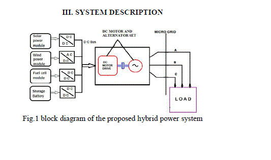
| Fig1 shows the block diagram of hybrid power system description. The hybrid power system in this paper is the
combination of the renewable energy sources such as, photo voltaic, wind power, fuel cell and also batteries. The PV,
fuel cell and batteries are giving dc output of different voltage levels and wind turbine output is a.c., we are choosing a
common dc-bus for the hybrid power system [3]. The output obtained from the renewable energy sources cannot be
directly fed to the load due to the voltage fluctuations, DC-DC/AC-DC converters are used to condition and provide the
constant voltage and it is given to the d.c bus. The local converters are acting in between the energy sources and the dc
bus and it boost up the voltage so as to meet the required dc bus voltage. The bus is parallel interconnection of all the
resources. From this, the dc power is fed to the further part of the system. Here the bus voltage is maintained at
300volts, which is the input voltage for DC motor. The dc motor is coupled with an alternator which runs at rated speed
as that of motor and generates 3 phase ac voltage, giving pure sinusoidal waveform which will be fed to the load at the
consumer side.The methodology which has been implemented in our work uses dc motor-synchronous generator set
instead of inverter that has to be connected between the dc bus and the loads. In this paper, PID controller provides the
control of speed for DC motor drive. DC motor is coupled with synchronous generator which runs at the same speed as
DC motor which in turn generates three phase pure sinusoidal voltage, which is given to the load. |
MODELLING AND SIMULATION |
| A. Inverter model: |
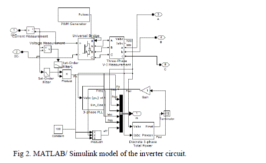
| Inverter is an electronic circuit which converts input dc voltage to three phase ac output voltages. For the
conventional HPS design, a three phase inverter circuit has to be designed. Fig. 2 shows the MATLAB/simulink model
of the inverter circuit. The parameters used in inverter modeling is given in table I |
| B. DC Motor- Generator set: |
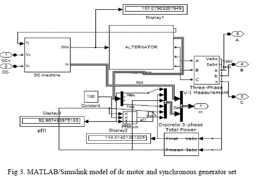
| In order to improve the power quality, the dc bus voltage is used to drive motor–synchronous generator set instead
of inverter as shown in fig. 3. For dc motor model, the input voltage is 300v, speed is 1500 rpm. The parameters
for alternator modeling are given in the table II.c |
| It is desired to maintain the power quality as high as possible irrespective of loads or environmental
conditions. This demands the system to have constant frequency, voltage and the output signal in sinusoidal shape etc.
It can be achieved by controlling the speed of the motor, as it is directly proportional to the frequency. For the
synchronous generator the speed is given by the equation. |
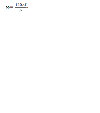 |
| Where Ns is synchronous speed (In rpm), |
| F is frequency, |
| P is number of poles. |
| C. Proposed HPS with Motor-Generator set: |
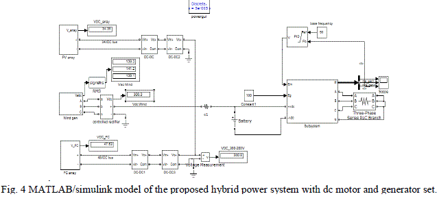
| Figure 4 shows the model for our proposed hybrid power system with dc motor-generator set. Initially all the energy
sources are connected to dc bus through boost converters. This bus provides the input to the MG set. The MG set
consists of dc motor coupled to an alternator, which supplies power to the loads. This technology provides voltage
stabilization and harmonic rejection. This arrangement will improve the power quality and overcome the major
drawbacks with the conventional HPS architecture |
| D. Energy management and control unit. The purpose of proposing the energy management and control unit is to make
proper utilization of electricity obtained from the various renewable energy resources. In the present work along with
the power quality issues which are associated with the power system, we are also concentrating on the energy
management between the various renewable energy resources and the load demands. Energy management and control
unit is included in our project work. The unit controls the flow of generated power as per the demands on the load side.
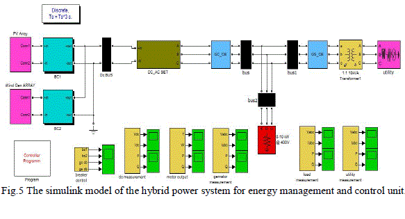
An algorithm is built for the energy management which controls the operation of the circuit breakers. The circuit breakers are placed on both renewable energy source side and the utility side. The EMCU continuously checks the
generation of power from renewable energy side, load demands and also at the utility side. |
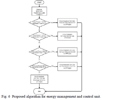
| The detailed explanation about the energy management is given in the form of flow chart. Under this we have checked
the operation of EMCU for different load conditions which is shown in figure 6. |
SIMULATION RESULTS |
| As per the aim of the present work, the results obtained are focusing on the power quality issues. Nowadays
electricity power quality has become a major issue. These require reliable and good quality power free from all quality
issues. Various critical parameters related to power quality are considered and they are Total Harmonic
Distortion(THD), Energy Conversion Efficiency Calculation(η), Shape of Output Waveform, Frequency variations,
Voltage sag and swell. |
| 1.Total Harmonic Distortion: The first and foremost consideration for the power quality issue is the Total Harmonic
Distortion (THD). |
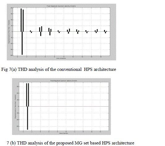
| Fig. 7(a) Shows the MATLAB/Simulink result for THD analysis for an inverter based HPS. It is observed that
harmonics are present throughout the output waveform in case of inverter and it is found 0.399% . Fig. 7(b) shows the
MATLAB/Simulink result for the THD analysis of the proposed MG set based HPS architecture. It is observed that
only the fundamental component of harmonic is present and the percentage of harmonic present is 0.04614%. Analysis
of the current wave is carried out with a fundamental frequency of 50 Hz. From the above results it is clear that the
presence of harmonics is higher in the conventional HPS with inverter than the proposed MG set based HPS
architecture. |
| 2.Energy Conversion Efficiency (η): |
| a).For inverter model: As inverter is a static device and does not have rotating part. So mechanical loss does not occur
in such devices. Losses occur in inverter only because of switching at high frequency. This type of losses are called
switching loss. Total losses in this model found to be very less, with an efficiency of around 95%. It is simply
calculated by the equation(3) given below |
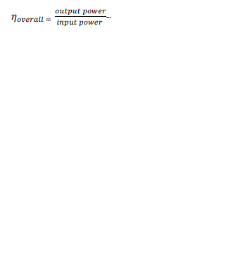 |
| Therefore, 95% |
| (b).For MG set: The output of any electrical machine is always less than the input, because some of the energy lost in
the form of heat during each stage of energy conversion. Therefore, this energy loss and the energy conversion
efficiency for the inverter based and proposed MG set based HPS is calculated as follows. |
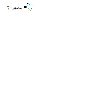
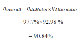
| Energy conversion efficiency of a dc motor is defined as given in equation (4) and denoted as . Therefore, |
 |
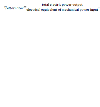
| Energy conversion efficiency of an alternator is defined as given in equation (5) |
 |
| The overall energy conversion efficiency of the MG set is as follows. Therefore |
 |
|
| As per the simulation, the results obtained are entered in table III. |
| 3.Output waveforms: |
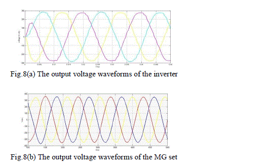
| One of the criteria to exhibit the good power quality is to have a pure sinusoidal waveform at the output side. Fig.8(a)
shows the waveform for the inverter output voltage. As it is observed, it is failed to obtain the pure sinusoidal
waveform due to the presence of ripple. Fig.8(b) shows the output voltage waveform of the MG set. As per the
simulation, the pure sinusoidal and balanced output voltage is obtained for all the three phases which is not in case of
inverter. This satisfies one of the conditions to have a good power quality and is achieved with our proposed MG set
mode. |
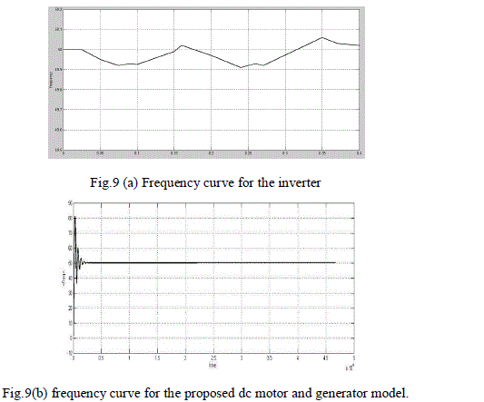
| 4.Frequency imbalance: As per the standards of the Indian utility power grid frequency should be constant at 50Hz but
the tolerance of ±3% is allowed. |
| Fig.9(a) shows the frequency curve for the inverter. The frequency of the inverter cannot be maintained constant due to
the frequent switching process. So we can see the variations in the frequency of the inverter. |
| Fig.9(b) shows the frequency of the proposed motor and generator set which is maintained constant at 50Hz
irrespective of the load condition. And from the figure if we observe the frequency will reach its highest value due to
the starting of the motor which will have the maximum current. But then within less than 0.5 seconds the system gains
the constant frequency. Simulation was done for various load conditions. And it is observed that the proposed model
maintains the system frequency at 50Hz for various load fluctuations. This is one of the good power quality
characteristics and thus it is achieved. |
| 5. Voltage imbalance: As per the IEEE standard the definition of voltage unbalance is the difference between the
highest and lowest rms voltage referred to the average of the three voltage. As per our simulation work the percentage
of voltage unbalance for the proposed motor generator set is 6%. And for the existing inverter model the voltage
unbalance is 14.4 %. Hence the proposed system shows its effectiveness. |
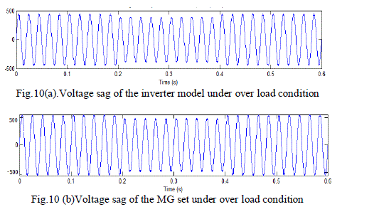
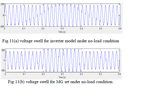
| 6. Voltage sag and swell: As per our simulation the graph obtained for voltage sag and swell for the inverter and
proposed MG set is shown below in figure 10(a) ,(b) and 11(a),(b) respectively. |
| In the fig 10(a) and (b) the sag is occurring in the interval of 0.2 to 0.4 seconds for both inverter as well as MG set.
And the circuit breaker is activated as long as the system retains the normal state i.e., till the sag disappears. The
percentage of sag is found out to be 7.48% in inverter and 1.57% in motor generator set. The voltage swell is also
analyzed in a similar way and is checked under no load condition for both inverter as well as MG set as shown in the
figure 11(a) and (b).The system is operated under no load condition for the time duration of 0.2 seconds. In that
duration of time the swell occurs. The percentage of swell in inverter is found as 8.66% and 1.96% in motor generator
set. The system is protected by circuit breaker which activates from 0.2 to 0.4 seconds. |
| Table IV presents the simulation results of the HPS related to power quality. |
| II. Energy management and control unit: |
| The energy management and control algorithm is proposed based on the generation of electricity from the renewable
energy sources and the different load conditions. In our work we have considered the four different load conditions
based on which the control algorithm is written. So all the conditions are simulated and the results obtained are given as
follows. The various parameters considered in the proposed algorithm are given in detail below. |
| Pl = load power in watts, |
| Pg = generated power from the renewable energy source side in watts, |
| Cb1 = circuit breaker after solar source, |
| Cb2 = circuit breaker after wind source, |
| Cb3 = circuit breaker after motor-generator set, |
| Cb4 = circuit breaker on the utility side. |
| I case: when Pl>= 0kw &Pg=<0 |
| This condition clearly says that the renewable energy source is not generating any power. Due to the unpredictable
weather conditions we have considered this case too. Suppose if there is no sun we can say rainy season we can hardly
expect sun to come out. In that case the power generated from solar is negligible or zero. Same way when there is less
wind velocity there will be no much power generated from the wind source. So we can say zero generation of power
from the RES. Thus it cannot supply power to the load. Now the load demand can only be fulfilled by the utility side.
The EMCU monitors the circuit breakers Cb1, Cb2, Cb3 on RES side to be in open condition and the circuit breaker
Cb4 on the utility side to be in closed condition.Which implies that the renewable energy source unit is isolated from
the load and now the nearest utility grid is exporting power to the load to meet the required demand?
So under this condition; Cb1=0, Cb2=0, Cb3=0(opened)
& Cb4=1(close). |
| II case: when 0kw=<Pl<5kw, Pg>0; |
| In this case the load demand lies between 0 to 5kw. In our hybrid system each unit is generating 5kw i.e.., solar unit is
generating 5kw and wind source is generating 5kw. Since the demand is less any one of the source can provide power
to the load. i.e.., either solar or wind source can be switched on to supply power to the load, which allows efficient
usage of energy without any wastage. In this case, when solar unit alone is supplying power to the load circuit breakers
Cb1 and Cb3 are activated and Cb2 is not activated. When wind source alone is supplying power then the circuit
breakers Cb2 and Cb3 will be on and Cb1 will be off. Since RES alone can meet the demand, the power is not drawn
from the utility side. |
| So; when 0<=Pl<5kw; Pg>0 |
| (a).When solar unit is supplying power, |
| Cb1=1, Cb3=1(closed) & |
| Cb2=0, Cb4=0(open). |
| (b).When wind source is supplying power; |
| Cb2=1, Cb3=1(closed) & |
| Cb1=0, Cb4=0(open). |
| III case: 5kw<=Pl<10kw, Pg>0 |
| Under this condition the load demand is in the range between 5kw to 10kw. Now the demand has increased compared
to previous case. Now according to the requirement both the sources i.e.., solar as well as wind have to generate power in order to meet the demand. And since the demand is within 10kw, power generated from RES alone is sufficient to
meet the load requirement. So load may not import power from the utility grid. So now the EMCU enables the circuit
breakers Cb1, Cb2, Cb3(close) and disables the circuit breaker Cb4(open). Now the entire power supplied to the load is
from hybrid power system and the utility grid is isolated from the load. |
| So; when 5kw<=Pl<10kw,Pg>0 |
| Cb1=1, Cb2=1, Cb3=1 (closed) & |
| Cb4=0(open). |
| IV case: when Pl>= 10kw &Pg>0, |
| This case checks when the load demand exceeds 10kw and also when there is sufficient generation of power from the
RES. Under this condition the power generated from RES alone will be not sufficient. Since there is extra requirement
of power to the load, the load imports the remaining power from the utility grid. The power supplied from the utility
grid to the load is the difference power between the load demand and the generated power from RES. And there will be
continuous generation from the RES unit. Thus at this point, the EMCU controls all the circuit breakers to be in closed
condition. |
| So ; Pl>= 10kw &Pg>0 |
| Cb1=1, Cb2=1, Cb3=1, Cb4=1 (closed). |
CONCLUSIONv |
| The paper focused on the combination of the PV, wind turbine, fuel cell and battery systems for the power
generation and to improve power quality. Most of the HPS use inverters to integrate the renewable energy source to the
buildings. An inverter is replaced by a dc motor-Synchronous generator model is proposed in this paper to investigate
the power quality issues. Power quality issues are investigated by simulating the hybrid power system with motorgenerator
set and the results are compared with the existing inverter model to prove the effectiveness of the proposed
one. From the results it is clear that the proposed system with new topology improves power quality. This can be
achieved by controlling the speed of dc motor-generator set by using the PID controller. And also the EMCU provides
the effective use of energy generated from the renewable energy side and makes the system more reliable. The
management of power leads to flexible switching of the renewable sources as well as reduces the utilization of power
from the utility grid. It also enables the maximum usage of energy which is generated on the renewable source side and
also would reduce the need of generation whenever the load demand drops. |
Tables at a glance |
 |
 |
 |
 |
| Table 1 |
Table 2 |
Table 3 |
Table 4 |
|
Figures at a glance |
 |
 |
 |
 |
 |
| Figure 1 |
Figure 2 |
Figure 3 |
Figure 4 |
Figure 5 |
 |
 |
 |
 |
 |
| Figure 6 |
Figure 7 |
Figure 8 |
Figure 9 |
Figure 10 |
 |
| Figure 11 |
|
References |
- C.Wang and M. H. Nehrir, “Power management of a standalone wind/ photovoltaic/fuel cell energy system,” IEEE Trans. Energy Convers.,vol. 23, no. 3, pp. 957–967, Sep. 2008.
- O. Omari, E. Ortjohann, A. Mohd, and D. Morton , “An online control strategy for DC coupled hybrid power systems”, in Proc. 2007IEEEPower Eng. Soc. Gen. Meet., pp. 1–8.
- E. Ortjohann, O. Omari, M. Lingemann, A. Mohd etc.., “An Online Control Strategy for a Modular DC Coupled Hybrid power System”.
- Y Jaganmohan Reddy, Y V Pavan Kumar, K Padma Raju, “Real Time and High fidelity Simulation of Hybrid Power System Dynamics”,Department of Electronics and Communication Engineering Jawaharlal Nehru Technological University Kakinada, Kakinada, AndhraPradesh, India..
- S. Ayasun and G. L. Karbeyaz, “DCmotor speed controlmethods using MATLAB/Simulink,” Comput.Appl. Eng. Educ., vol. 15, pp. 347–354,2007.
- Mohd1, E. Ortjohann, W. Sinsukthavorn1, M. Lingemann1, N. Hamsic, D. Morton, “Supervisory Control and Energy Management of anInverter-based Modular Smart Grid”, South Westphalia University of Applied Sciences/Division Soest ,The University of Bolton, DeaneRoad, Bolton, U.K.
- K. De Brabandere, K. Vanthournout, J. Driesen, G. Deconinck, and R. Belmans, “Control of microgrids,” in Proc. 2007 IEEE Power Eng.Soc.Gen. Meet., pp. 1–7.
|