Keywords
|
| Fractal Array, Cantor Set, Radiation Characteristics, Uniform Linear Array. |
INTRODUCTION
|
| A. Fractal Geometry |
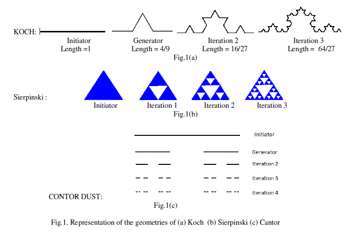
| A man is confronted by many undescribed shapes in the universe [1]. The shapes of the sea coasts and leaves which are not circles, clouds which are not spherical, hills are not conical, and path of a lightening which is not straight line are some of them to name[2]. This is due to the constraint of the Euclidean geometry in representing the shapes in dimensions only in whole numbers. Fractal geometry is the solution for this. Since the fractal geometry took the role of explaining undescribed shapes, it captured the attention of many engineers from many disciplines. This is made possible with key feature of fractal geometry in describing the dimensions in fractals along with whole number like 1D,2D and 3D. Fractal can be defined as an irregular geometric representation with an infinite nesting of structure at different scales. This made it possible to describe any object in the universe with a unique dimension. The well known fractal geometries with extensive applications in antennas are Sierpinski, Koch, Contor, Hilbert Curves etc [3]. The Structure of various Koch, Sierpinski and Cantor are as shown in the fig. 1(a) through 1(c). |
| B. Fractal Array |
| Improved Directivity, capability of Beam Steering, Beam Forming, Control over the Beam Width, Arrangement of Nulls in the desired direction are some characteristics that are possible with Arrays with which they have proved to be the ultimate choice over single element antennas. In the due course they occupied a paramount role in Electromagnetics, Wireless Communications etc. Since their first application it observed many variations, whether it may be the case with its geometry, type of excitation or choice of elements of the array. With the same trend when the galaxy of electromagnetic engineers are fascinated by the concept of applying fractals for their regular applications in communications, the arrays have also started adopting them for some specific reasons. |
FORMULATION
|
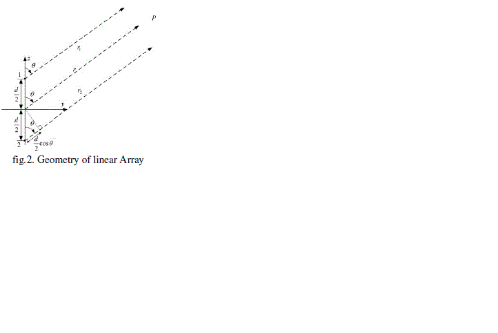
| The geometry of the array that is considered is as shown in the fig.2. The elements are arranged on a straight line to depict a linear array. |
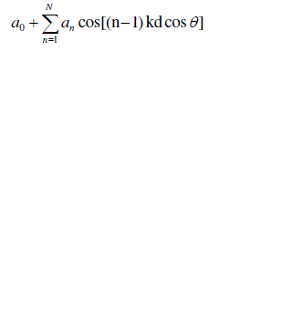
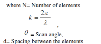
| The corresponding array factor for the above mentioned array in which uniform spacing and non uniform amplitude distribution is considered is given as [4] |
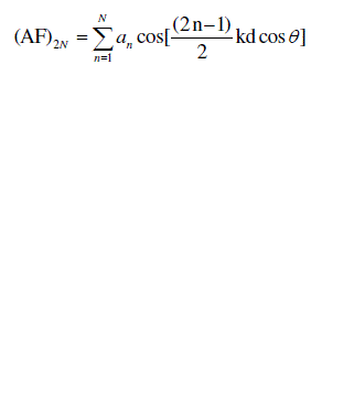 |
| for array of even number of elements |
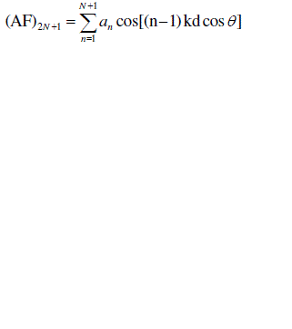 |
| for array of odd number of elements |
 |
 |
| For simplicity we consider the amplitude distribution to be uniform and unity to conveniently transform to cantor array. Now we can compare the generator form of the cantor as shown in the fig. 1(c) with a linear array of 3 elements with the excitation to the extreme end elements as 1's and centre element as 0. Now this is considered as generator element array. The next generation cantor is obtained by replacing 1's in the previous array with '101' and 0's with '000'. The same is repeated over generations. This is tabulated in the table(1). |
| The distribution can be formulated as [5,6,8] |
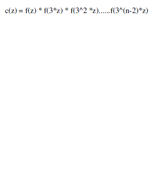 |
| where c(z) is cantor set and the f(z) is function generator analogous to equation (3). With the aid of the above discussion we can arrive at the following equations |
for generator set the array factor can be represented as 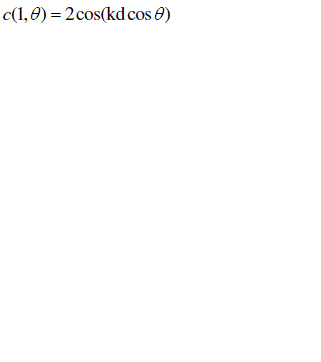 |
whereas for iteration 2 it is given as 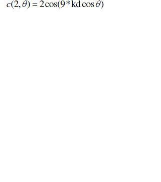 |
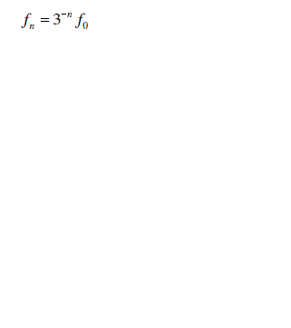
likewise after n-iterations 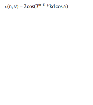 |
| Similarly the multiband characteristics for frequencies other than the fundamental resonating frequency [5,7] is given after n iterations as |
 |
SIMULATION RESULTS
|
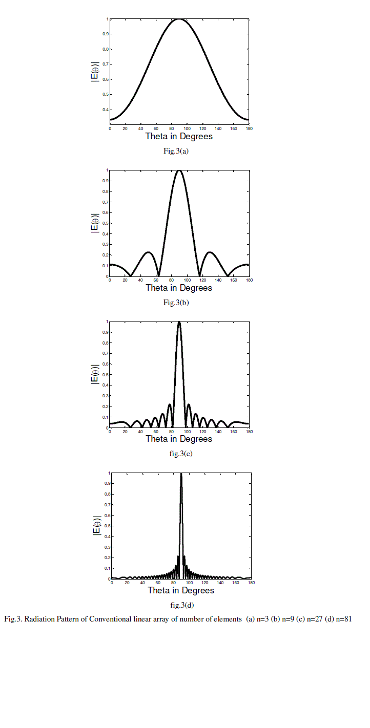
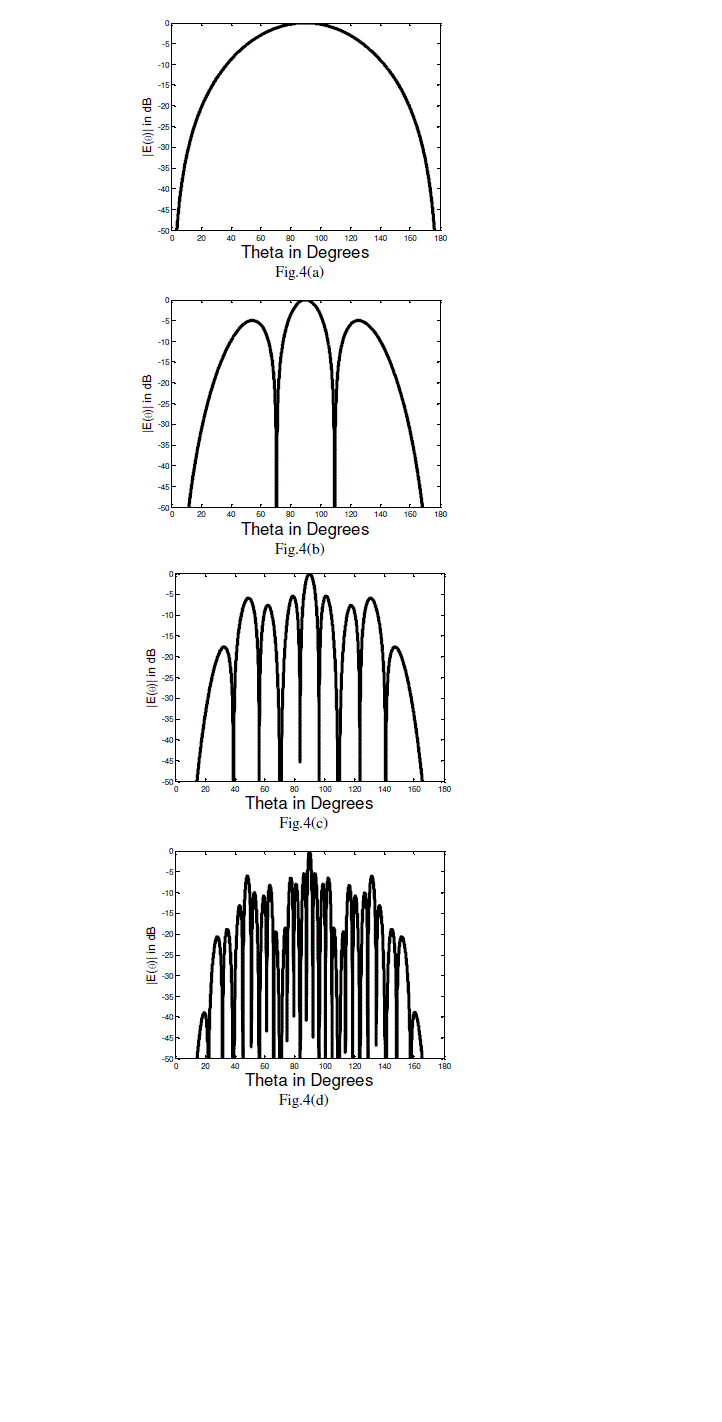
| The radiation characteristics with u= cosθ domain are simulated in MATLAB environment on i3 processor. The radiation characteristics of conventional array for number of elements n=3, n=9, n=27 and n=81 for a spacing d of λ/4 for an operating frequency of 8.1 GHz are as shown in the Fig.3(a) through 3(d). Scan angles theta in degrees is plotted on x axis and the corresponding normalised E field values based on the array factor are plotted on the y-axis. |
| For the same spacing and operating frequency a cantor array weights are generated over iterations of i=1, i=2, i=3 and i=4. The corresponding radiation pattern is plotted as shown in the Fig.4(a) through 4(b). |
CONCLUSION
|
| The radiation characteristics of the Cantor Fractal Array are plotted. They can be compared with conventional linear array to observe that there is considerable decrease in the side lobe level as well as thinning of the beam. It is observed that over iterations, two consecutive bands have common nulls. This is clear from the equation (4) through (8). The directivity characteristics over various resonating frequencies is disappointing. The directivity of the generating subarray and that of the second iteration are same. |
ACKNOWLEDGMENT
|
| The first author would like to acknowledge the support from Sri Raghu Kaladindi, Chairman, Raghu Educational Society, Visakhapatnam. |
Tables at a glance
|
 |
| Table 1 |
|
Figures at a glance
|
 |
 |
 |
 |
| Figure 1 |
Figure 2 |
Figure 3 |
Figure 4 |
|
References
|
- Jampala, S., "Fractals: classification, generation and applications," Circuits and Systems, 1992., Proceedings of the 35th Midwest Symposiumon , vol., no., pp.1024,1027 vol.2, 9-12 Aug 1992. doi: 10.1109/MWSCAS.1992.271120
- B. B. Mandelbrot, The Fractal Geometry of Nature, 1983 :W. H. Freeman
- Anguera, J., Puente, C., Borja, C. and Soler, J. 2005. Fractal Shaped Antennas: A Review. Encyclopedia of RF and Microwave Engineering.
- Constantine A. Balanis, Antenna Theory, 2ed, Wiley.
- Carles Puente-Baliarda, Rafael Pous., "Fractal Design of Multiband and Low Side-Lobe Arrays,"IEEE Transactions on Antennas andPropagation, Vol.44, No.5, May 1996.
- A.Alexopoulos., "comparison of conventional and fractal shaped phased array," DSTO-TN-0913, Oct' 2009.
- Mushiake, Y.; "Self-complementary antennas," Antennas and Propagation Magazine, IEEE , vol.34, no.6, pp.23-29, Dec. 1992doi: 10.1109/74.180638.
- R.T.Hussain, and F.J.Jibrael, "Comparison of the radiation pattern of fractal and conventional Linear Array", PIERS, Vol 4, 183-190, 2008.
|