Keywords
|
| CDMA, Power Control, SIR, Open loop power control, Closed loop power control, Distributed Balancing algorithm. |
INTRODUCTION
|
| Power is a fundamental concept in wireless communication systems, because the received power is the signal strength to the desired receiver and is interference to all other receivers. Power is the term that limit the system capacity. Transmitter power control is an efficient technique to limit the interference under fading conditions, remove the near far problem and increase the battery life. So effective power controlling in communication systems can offer a better improvement in quality of service. Power control adjust the transmitted power in order to maintain the SIR (Signal to interference ratio) at a given level and this level is fixed according to the bit error rate and estimated on the basis of received BER and estimated BER for the system. |
| The conventional power control methods used in communication systems can be divided into open loop control and closed loop control. Due to the difference between the forward and reverse link propagation losses, it is impossible to use open loop control to get effective power control. So closed loop control is effective power control technique. This means that the base station sends one bit command to the user to either raise or lower mobile’s power by comparing the received power with the present power level. There are various power control techniques like Distance based, Distributed balancing. Power control is needed in CDMA systems to compensate for the interference caused by high powered mobiles against weak ones near the base station |
II. CELLULAR CDMA CAPACITY
|
| In cellular CDMA several users can transmit messages simultaneously over the same radio bandwidth, each using a specific spread-spectrum pseudo-noise (PN) code. Since these codes cm not be exactly orthogonal for a set of asynchronous users, in addition, in mobile environment the synchronization between the users in uplink is impractical. Inter-user interference usually adds on the power basis and the radio link performance of any one user becomes poorer as the number of simultaneous users increases. |
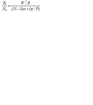
| The Effect of interference on the Capacity of CDMA System Here 1 will focus on the reverse link (user to cell site) capacity, because the forward link (cell site to user) employs coherent demodulation by pilot carrier, which is being tracked, and since the multiple transmitted signals are synchronously combined, its performance in a single ce11 system is likely to be superior to that of the reverse link . While in the reverse direction, the operation between ail users is not coordinated, non-coherent reception and independent fading of al1 users is assumed. Thus, the emphasis is on the evaluation of reverse link capacity and we assume that the capacity in the forward link will be better than or at least equal to that found on the reverse link. .Assuming with power control, al1 reverse link signals are received at the same power level, i.e. for N users, the ce11 site processes the desired signal having power P and (N-1) interfering signals each also having power P. Given the fact that bit energy Eb and the noise density N0 can be expressed as: |
 |
| where |
| N - number of users per cell. |
| R - information bit rate. |
| W - total spread spectrum bandwidth. |
| - background noise (including thermal noise distributed over the total bandwidth W). |
| P - received power from each user. |
| Then |
 |
| Where |
| W/R - processing gain. |
| Eb/No- bit energy-to-noise density ratio, commonly called signal-to-noise ratio SNR, its value must ensure the adequate performance of the modem and decoder. It is noticed that the number of users have to be reduced if the required SNR increases. It was shown that the voice signals are intermittent with an activity factor of approximately 3/8. It suggests that capacity can be increased by an amount inversely proportional to this factor by suppressing transmission during the quiet period of each speaker to reduce interference. Similarly any spatial isolation through the use of directional antennas (sectorization), which reduces interference, also provides a proportional increase in capacity. Sectorization means that directional antennas are used at the ce11 site both for receiving and transmitting. For example, with three antennas per site, each having 1200 effective beam-widths, the interference sources seen by any antenna are approximately one-third of those seen by an Omni-directional antenna. Henceforth, using three sectors, the number of users per cell can be increased three times as much capacity. |
| Taking the effect of voice duty and sectorization, the actual average SNR can be written as |
 |
| where |
| Ns - number of users per sector. |
| α- voice duty factor |
| It is shown in that taking voice duty factor of 3/8 and sectorization of 1200 into account, the average number of user per cell can be increased by a factor of 5 or 6. In CDMA the capacity is only interference limited, any reduction in interference converts directly into an increase in capacity. |
III.DISTRIBUTED BALANCING TECHNIQUE
|
| Let Ni (positive integer) denote the number of communicating mobile in cell i (i=0,1….,18), Bj denote the base j (j=0,1,…….,18), Mik denote the mobile k (k=1,2,…., Ni) in cell i, Ziki , denote the link gain from Bi to Mik, and Pik denote the down-link power transmitted from Bi to Mik. Since self-jamming is much more dominant on received SIR (= S/I; signalto- interference ratio) than background noise, so it is neglected in this simulation. Therefore, the SIR of Mik, denoted by SIRik , can be expressed as-: |
 |
| If the signal-to-noise ratio at any mobile station has been balanced by our DB power control process, regard that SIRik is independent of mobile k in cell i. i.e., SIRik = SIRi= constant for fixed i. So rearrange Equation and obtain Pik given by |
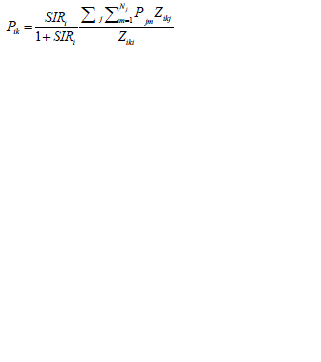 |
| Equation implies that the optimal transmitted power assignment for Mik is proportional to the ratio of the total received power of this mobile to the link-gain between its home base and itself. |
IV. SIMULATION RESULT
|
| The performance of this power control algorithm is simulated using MATLAB. In this paper four different type of signal with their iteration values are modelled. No receiver diversity is modelled results in very weak and high variations of signal strength at the receiver. Simulation parameters are summarised in table: |
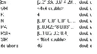 |
| where SIR-Signal to Interference Ratio |
| GM-channel gain matrix; RSIR- RSIR-Required SIR at each receiver |
| PA-power available at each transmitter, N-noise at each receiver |
| Err-Error Difference between required SIR and actual SIR |
| N- Noise power at each receiver |
| K- Number of user |
| RSIR- Target SIR at each receiver |
V.CONCLUSION
|
| In this project, four different type of signals analyzed based on outage versus number of iterations. The Distributed Balancing (DB) power control algorithm was shown to give better results compared to Distance Based Power Allocation (DBPA) algorithm. In this paper various parameters are used to improve the output result. |
Figures at a glance
|
 |
| Figure 1 |
|
| |
References
|
- Ariyavisitakul, S., Li, F., “Signal and interference Statices of a CDMA system with feedback power control” Trans. Comm., Vol. 41 No. 11,November, 1993.
- Akinniyi, A.R., Lehnert, J.S. “Characterization of Noncoherent spread spectrum multiple access communications” IEEE transaction oncommunication. Vol. 42, No. 1, January, 1994.
- Bottomley G.E. , “ Signature sequence selection in a CDMA system with orthogonal coding” IEEE transaction on vehicular technology, Vol. 42, No. 1, Feb. 1993.
- Chang,Chung-Ju& Ren,Fang-Ching,“Downlink Power Control in DS/CDMA Cellular Mobile Radio Network” In Proc. 3rd International Conf. on Universal Personal Communications (ICUPC’94), pages 89–93, San Diego, CA, 1994.
- Cooper,G. and Neetleton, R. “ A spread spectrum technique for high capacity mobile communications” Trans. On vehicular technology, Vol. 27 No. 4, November, 1987.
- Cox,D. “CochannelInterferance considerations in frequency reuse small coverage area radio system” Trans. No. communication, Vol. VT-30, No. 04, January, 1982.
- Felhaure, T. , Klein, A. and Baier, P.W. “A low cost method for CDMA and other application to sepatate non orthogonal signals” IEEE transaction on communication.
- Gilhousen, K. , Jacobs, I. , Padovani, R. , Viterbi ,A. , Weaver, L. and Wheatley, C. “On the capacity of a cellular CDMA system” Trans. OnVehicular technology, Vol. 42 No. 4, November, 1991.
- Grandhi, S.,“Centrilized power control in cellular radio systems” Trans.On Vehicular tech. vol.42 No. 4,November, 1993.
- Grandhi, S. “Distributed power control in cellular radio systems” IEEE Trans. On com. vol. 42 No. 1/3/4, Feb., March, April, 1994.
- Glance ,B. and Greenstein, L. “Frequency-Selective Fading effects in digital mobile radio with diversity combining” Trans on com. Vol. Com. 31 No. 9, September, 1983
- Geraniotis E., and Pursley M., “ Performance on Choerent direct sequence spread spectrum communication over spiculer multipath fedingchannel” Trans. On Communication, Vol. com. 33, no. 6, June , 1985.
- Geraniotis, E.A., Parsley, M.B. “Performance of coherent direct sequence spread spectrum communication over speculer multipath feding channel”IEEE trans on com. Vol. com 33, No. 6, June, 1985.
|