Keywords
|
| Sub threshold leakage; VBBK; Zigzag; Sleep transistors; Stacking |
INTRODUCTION
|
| Low power consumption has become important factor in recent electronics industry due to rapid growth of battery operated devices like laptop, PDAs, cellular phones and other communication devices. For high performance and high packaging density, supply voltage and threshold voltage is constantly scaled down. But this leads to increase the sub threshold voltage, which in turn increases the power consumption. Static consumption is major contributor of total power consumption which is due to leakage current flowing when the device in the standby mode. Sub threshold leakage current is most predominant of all leakage current and becomes challenging for VLSI design engineers. It is drain to source current flowing when the transistor is operating in weak inversion region. The sub threshold leakage current is given by |
 |
| Where VÃâ ß is the thermal voltage, γ is the body bias coefficient, η is drain-induced barrier lowering coefficient. |
| Based on mode of operation leakage power reduction is classified as standby mode and active mode. In standby mode, the circuit is in idle state and is cut off from the power rails. During active mode, leakage power is reduced by stacking up the transistors. |
II. PREVIOUS WORK
|
| Here we review prior work that is related to our research. In this section we classify the circuits based on state retention and state destructive logics. |
| This section describes previously proposed low power reduction for generic logic circuits. We classify them based on (i) Save state and (ii) Destructive state. |
| SLEEP TRANSISTOR: Here sleep transistors are used between the power rails to cut off the power supply when the device is in the idle mode. So this technique is commonly power gated technique. A technique called multi threshold voltage CMOS transistor proposed by Motoh et al.[2] uses high Vth sleep transistors and low Vth transistors in pull up and pull down device to maintain high switching speed. Sleep transistors are turned off when the device is in idle state, which dramatically reduces the leakage power in standby mode. During active mode the device works normally. |
| FORCED STACK: Transistor stacking is the technique where the leakage power is suppressed greatly. Narendra et al changed the effective channel length of the stacked transistor and found that there is considerable reduction of sub threshold leakage power [3]. Here (W/L) ratio of the transistor is broken into two halves, so the transistor turns off/on simultaneously. Sub threshold current is thus reduced with area and delay overhead, thus saving the state of device. |
| SLEEPY STACK: Sleepy stack is combination of Sleep and forced transistor technique. Forced transistor breaks the transistor into two halves whereby leakage power is reduced. Sleep transistor technique retains the logic state and saves the power when its sleep mode [4][5]. It uses two additional sleep transistors parallel to the existing sleep transistor, whereby the area and delay gets increased. During idle mode, sleep transistor are turned off and the power is substantially reduced. During active mode, sleep transistors are on and delay is reduced as there is active resistance path |
| SLEEP APPROACH: This approach reduces the area overhead caused by the additional sleep transistor used in the sleep approach. By placing alternate sleep transistors [6], this area overhead can be reduced. In sleep mode, input of logic is “0” and each logic input reverses its state and the output is 1. Thus, the zigzag approach uses few sleep transistors than the sleep logic. |
| SLEEPY KEEPER: In this approach, PMOS transistor is placed parallel to the pull up sleep transistor and NMOS is placed parallel to pull down sleep transistor [7]. When in sleep mode, the NMOS is the only source of VDD to pull up network as the sleep transistor is turned off. When in active mode, PMOS is the only source of ground to pull down network as the sleep transistors is turned on. Due to the presence of sleep transistor, the resistance of the ON path increases thus decreasing the propagation delay. This approach retains the logic state of the circuit |
III. STRUCTURE
|
| We introduce our proposed methodology “variable body biased keeper”. Then we explain this technique applied for the generic logic circuits. The proposed structures are combination of forced stack and sleep with variable body bias technique. The sleep transistor technique retains the logic state of circuit while forced stack maintains the minimum delay penalty. Thus this reduces the leakage power while saving the logic state. |
| There are two modes of operation, active mode and sleep mode. The SSVBB has a structure merging forced sleepy stack with variable body biasing technique. The sleepy stack divides the existing transistors into two halves while maintaining the input capacitances. Then the sleep transistors are added in parallel to stacked pull up and pull down transistors. During active mode, s=0 and s’=1 are asserted, thus all sleep transistors are turned on thus reducing circuit delay. The performance is improved as the body to source of the PMOS is ON, which lowers the Vth of PMOS transistor again. Due to body effect, Vth decreases thus increases the performance. As the sleep transistors are always on there is faster switching time than the forced stack. During sleep mode, s=1 and s’=0 are asserted, so both of the sleep transistor are turned off, thus maintaining the logic state of the circuit. As a result of body effect, Vth increases, which decrease the performance |
IV. EXPERIMENTAL METHODOLOGY
|
| The proposed structures are combination of forced stack and sleep with variable body bias technique. The sleep transistor technique retains the logic state of circuit while forced stack maintains the minimum delay penalty. Thus this reduces the leakage power while saving the logic state. |
| There are two modes of operation, active mode and sleep mode. The SSVBB has a structure merging forced sleepy stack with variable body biasing technique. The sleepy stack divides the existing transistors into two halves while maintaining the input capacitances. Then the sleep transistors are added in parallel to stacked pull up and pull down transistors. During active mode, s=0 and s’=1 are asserted, thus all sleep transistors are turned on thus reducing circuit delay. The performance is improved as the body to source of the PMOS is ON, which lowers the Vth of PMOS transistor again. Due to body effect, Vth decreases thus increases the performance. As the sleep transistors are always on there is faster switching time than the forced stack. During sleep mode, s=1 and s’=0 are asserted, so both of the sleep transistor are turned off, thus maintaining the logic state of the circuit. As a result of body effect, Vth increases, which decrease the performance. |
V. EXPERIMENTAL RESULTS
|
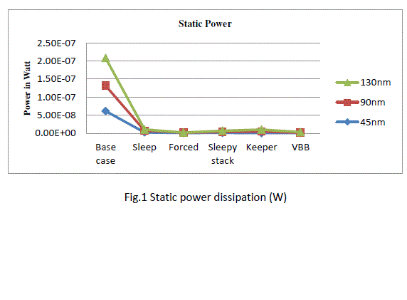
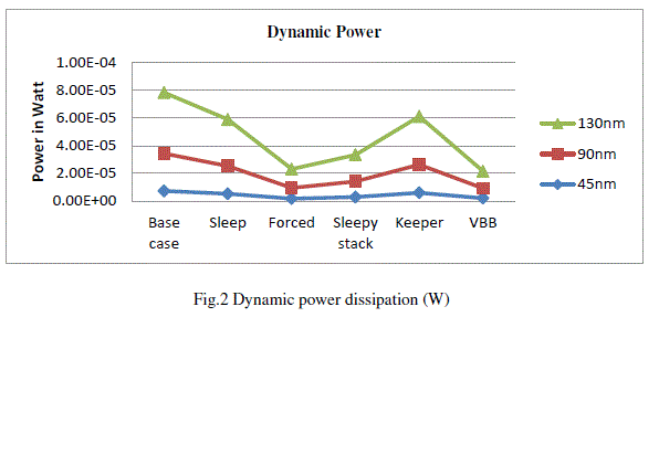
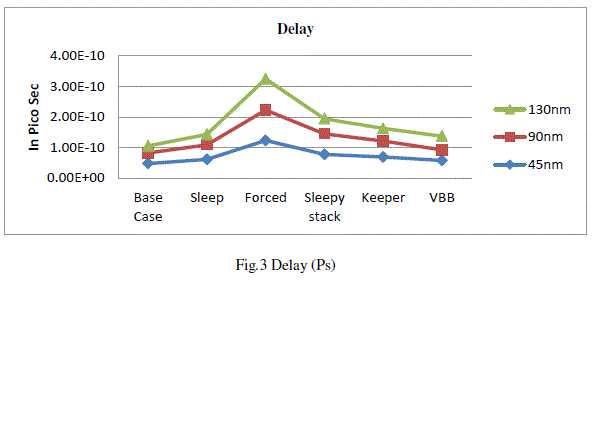
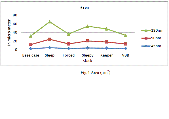
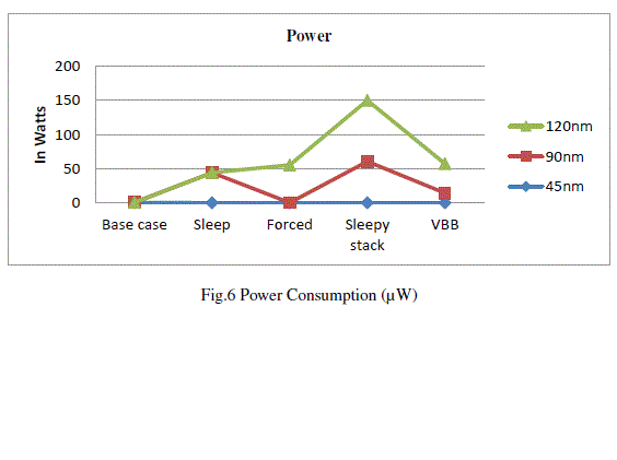
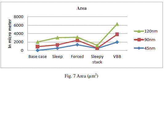
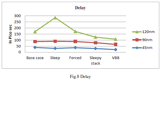
| We measure static power dissipation, dynamic power dissipation, propagation delay and area for the four approaches namely, sleep, sleepy stack, forced stack and base case with the proposed method. The simulation is performed using schematic entry and its corresponding test patterns are generated and its functionality is verified. After verification, the schematic file is converted into Verilog file, which gets converted into physical layout. Using the physical layout the area and delay is found. |
| All the approaches are compiled with single Vt method. The inverter uses W/L = 6 for PMOS in the pull up network and W/L = 3 for NMOS in the pull down network. All the simulations are carried down at the room temperature of 270C, VDD= 1.2v, supply voltage of 2.5V. The device model used for the simulation is BSIM model. |
| TEST CIRCUITS: Chain of inverters, Full adder and SRAM cell is chosen as benchmark circuits. A chain of inverter is chosen as a basic circuit as every transistor level implementation has the characteristics of an inverter. Full adder is chosen as basic building block and is constructed from logic gates and two inverters. SRAM is a basic memory and is constructed with inverters and pass transistors. |
| CHAIN OF FOUR INVERTERS: Three inverters of equal size are connected as shown in the diagram. Our approach is compared with the base case, forced stack, sleep and zigzag in terms of power dissipation, area and delay. Dual Vt is also applied along with single Vt approach. |
| Full Adder: A full adder is created from logic blocks that generate sum and carry along with two inverters. The complex blocks are sized with NMOS W/L = 3/1, PMOS W/L = 9/1. |
VI. CONCLUSION
|
| In this paper we have presented a new leakage power reduction scheme “Variable sleepy biased keeper”. It provides large power saving among all the alternative schemes. There is 51% power savings compared to base case. But there is area overhead with increase of 58%. |
| For future work, we will explore how process variation affects leakage power using Variable sleepy biased keeper. |
Figures at a glance
|
 |
 |
 |
 |
| Figure 1 |
Figure 2 |
Figure 3 |
Figure 4 |
 |
 |
 |
| Figure 5 |
Figure 6 |
Figure 7 |
|
| |
References
|
- International Technology Roadmap for Semiconductors (ITRS-05).http://www.itrs.net/Links/2005ITRS/Design2005.pdf.
- Mutoh, S., Douseki, T., Matsuya, Y., Aoki, T., Shigematsu, S., and Yamada, J., “1-V Power Supply High-speed Digital Circuit Technology with Multi threshold-Voltage CMOS,” IEEE Journal of Solid-State Circuits, vol. 30, no. 8, pp. 847–854, August 1995.
- Narendra, S., S. Borkar, V. D., Antoniadis, D., and Chandrakasan, A., “Scaling of Stack Effect and its Application for Leakage Reduction,” Proceedings of the International Symposium on Low Power Electronics and Design, pp. 195–200, August 2001.
- J.C. Park, V. J. Mooney III and P. Pfeiffenberger, “Sleepy Stack Reduction of Leakage Power,” Proceeding of the International Workshop on Power and Timing Modelling, Optimization and Simulation, pp. 148-158, September 2004.
- J. Park, “Sleepy Stack: a New Approach to Low Power VLSI and Memory,” Ph.D. Dissertation, School of Electrical and Computer Engineering, Georgia Institute of Technology, 2005.
- K.-S. Min, H. Kawaguchi and T. Sakurai, “Zigzag Super Cut-off CMOS (ZSCCMOS) Block Activation with Self-Adaptive Voltage Level Controller: An Alternative to Clock-gating Scheme in Leakage Dominant Era,” IEEE International Solid-State Circuits Conference, pp. 400-401, February 2003.
- S. Kim and V. Mooney, “The Sleepy Keeper Approach: Methodology, Layout and Power Results for a 4 bit Adder,” Technical Report GITCERCS- 06- 03, Georgia Institute of Technology, March 2006, http://www.cercs.gatech.edu/tech-reports/tr2006/git-cercs-06-03.pdf .
- B.S. Deepaksubramanyan and Adrian Nu˜nez, “Analysis of Subthreshold Leakage Reduction in CMOS Digital Circuits”, Proceedings of the 13th nasaVLSI symposium, post falls, idaho, usa, june 5-6, 2007.
- VolkanKursun, Eby G. Friedman, “Domino Logic With Variable Threshold Voltage Keeper”, IEEE transactions on very large scale integration (VLSI) systems, vol. 11, no. 6, December 2003
- VolkanKursun, Eby G. Friedman, “Forward body biased keeper for enhanced noise immunity in domino logic circuits”,IEEEtransactions on very large scale integration (VLSI) systems, 2004
|