INTRODUCTION
|
| Fault analysis in the solar PV arrays is a fundamental task to eliminate any kind of dangerous and undesirable situations arising in the operation of PV array due to the presence of faults. They must be detected and cleared off rapidly. The faults occurring in the PV arrays are – Ground faults, line-line faults, etc. In addition to these, there exists many undesirable operating conditions - Partial shading, reverse connections, changing illuminations, etc. |
| Ye Zhao et al[1][2][3] have discussed about the various challenges in line-line fault analysis and protection against these faults, particularly during two unique scenarios – Low irradiance conditions and Night-to-day transition. They also have discussed about the challenges to Over-Current Protection Devices (OCPDs) brought by the MPPT (Maximum Power-Point Tracker)[4]. They also have tried to propose two methods of fault detection – Decision-tree based fault detection[5] and Outlier Detection Rules[6]. |
| Mohammed KhorshedAlam and Faisal H. Khan[7] have discussed about the different types of faults and fault detection techniques and also proposed about the transmission line model for PV panels, which can be useful for interpreting faults in PV using reflectometry methods. |
| A Chouder and S Silvestre[8] have discussed about the automatic supervision and fault detection of PV systems based on power losses analysis. It analyzes the faulty signal and the current/voltage ratios and identifies the type of fault. |
| T Shimakage et al[9] have discussed about the development of fault detection system in PV panel. XiaoliXu et al[10] proposed the new current and voltage detection method to predict and locate the fault occurrence rapidly and accurately |
| N Pandiarajan and RanganathMuthu[11] have explained step-by-step for Simulink modeling of Solar PV module |
| This paper presents the analysis of solar PV module under faulty conditions and the recently proposed Outlier Detection Rule is planned to be utilized for fault detection |
II. FUNDAMENTALS OF PV SYSTEMS
|
| The term ‘photovoltaic’ means the ‘production of electric current at the junction of two substances exposed to light’. Here, in solar PV system, the electron gains the energy from the photons (in the solar radiation) and starts moving, constituting electric current. Thus, the solar PV cell works. The output of the cell is in the order of few Watts. In order to achieve higher power rating, these PV cells are connected in series and parallel to form a solar module. This PV module is operated in two modes – Stand-alone in remote areas where the power demand is lower and the extension of transmission lines is uneconomical, hybrid where the continuous supply of electricity is needed, combined with wind energy, diesel generator, battery back-up, etc. or combinations of these three and the output is connected to the grid. |
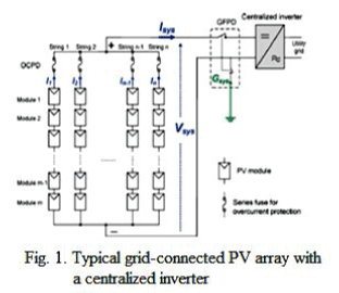
| A typical grid-connected PV system consists of several major components – PV modules, power conditioning unit with MPPT algorithm, wirings and protection devices – Over-Current Protection Devices (OCPDs) and Ground Fault Protection Devices (GFPDs) as in fig. 1 [1][2][3]. |
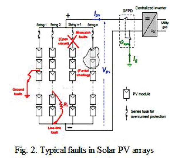
| A solar PV array is extremely susceptible to the faults – Line-line, Ground, Shading, Open-circuit, Mismatch, etc. as in fig. 2 [5]. |
III. MODELING OF PV SYSTEM AND FAULT DETECTION
|
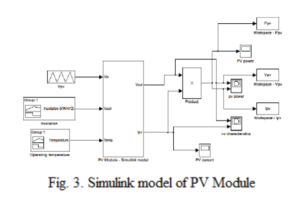
| PV system is modeled in MATLAB/Simulink as in fig. 3. The block ‘PV Module – Simulink Model’ consists of six subsystems, each representing the equations below. The equations concerned with the modeling of the PV system are [11]: |
 (1) (1) |
 (2) (2) |
 (3) (3) |
 (4) (4) |
 (5) (5) |
 (6) (6) |
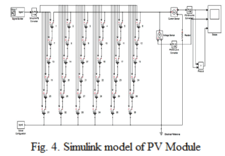
| Alternatively, another model of PV module has been developed for facilitating the representation of faults as in fig. 4. |
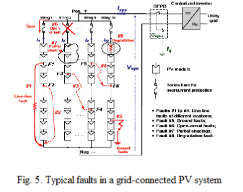
| The different types of faults occurring in the solar PV systems are as shown in the fig. 5 [6]. The faults will damage solar PV system, cause fire and safety hazards, reduce reliability, lifetime and performance. These may result in disadvantage for PV system. |
| The different types of fault detection methods so far discussed are – current and voltage detection method [10], comparison of the output parameters under faulty and normal conditions [9] and power losses analysis [8], reflectometry methods [7], outlier detection rule [6] and decision tree-based fault detection [5]. All these different methods are discussed briefly below. |
| Current and voltage detection method utilizes the voltage and current sensors to detect the possibility of the damaged module. This method is very accurate and is used to conduct real-time fault detection of solar PV arrays [10]. |
| The method discussed in [9] helps us to determine the performance ratio (before fault and after fault). They utilize irradiance, air temperature and AC output from the system. The comparisons of the actual output and the estimated output are performed and then it is determined whether fault is present or not. |
| The effect of fault on the output voltage and current is utilized in [8]. The PV panel under normal conditions, gives higher output than the PV array under fault conditions |
| The method discussed in [7] proposes the transmission line model for PV panels that can be useful for interpreting faults in PV using different reflectometry methods. |
| The outlier detection rule [6] utilizes the measured values of the various parameters and checks for any anomalous data, if present, which is outlier. There are 3 rules – Hampel identifier, Boxplot rule and 3-Sigma rule |
| The method in [5] uses a trainer kit for making any decisions. This method is disadvantageous in case of cost, but accurate. The trainer kit has to be programmed for the values of various parameters (irradiance, voltage, current, operating temperature). |
IV. FAULTS AND MODELING OF PV SYSTEM UNDER FAULTS AND OUTPUTS
|
| Line-line faults under two unique scenarios are discussed in this section. As in [1], the magnitude of the backfed fault current depends on the irradiance levels. Hence, if the fault occurs during the periods when irradiance is low (during morning, evening or during cloudy days), the fault current is lower than the OCPD rating, hence, the relay will not be able to detect and clear the fault. Hence, the fault lays hidden. If the system is connected with MPPT, the fault current is lowered down by the MPPT, hence, the fault isn’t cleared even during the high-irradiance period later in the day. But, if the fault occurs during high irradiance, it gets cleared by the OCPDs [1][2][4] |
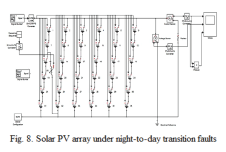
| In the similar way, as in [3], during night, when there is no irradiation present, if the fault occurs, there will be no (or very low) fault current, hence the fault is not at all likely to be cleared. As the night-to-day transition occurs, the system with MPPT again responds faster than the irradiation, hence, the fault current is lowered, the OCPD doesn’t work properly [1][3][4]. |
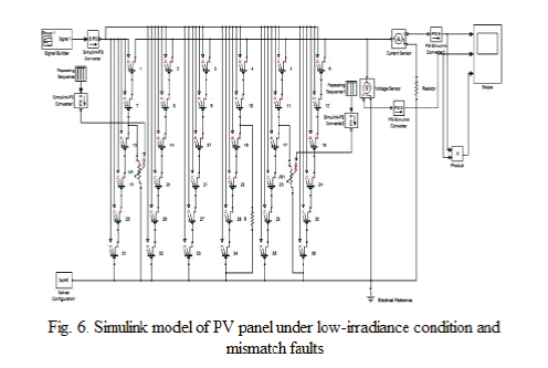
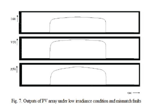
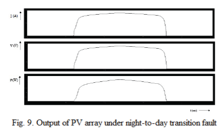
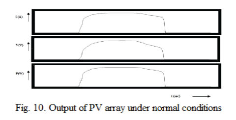
| As in fig. 6, the fault in Ist string and the last string are low irradiance conditions. The fault in the IVth string is mismatch fault. The outputs obtained are shown in fig. 7. Similarly, the fault during night-to-day transition is shown in fig. 8 and the corresponding outputs in fig. 9. The PV array output under normal conditions is shown in fig. 10. |
| The power output during normal conditions is 2.53 W (V = 3.6 V, I = 0.72 A, Rsh = 5 ohms). The power output during fault conditions (low irradiance and mismatch conditions in this case) is 0.34 W (V = 1.3 V, I = 0.26 A, Rsh = 5 ohms) and during night-to-day transition in this case is 2.45 W (V = 3.5 V, I = 0.7 A, Rsh= 5 ohms). |
Figures at a glance
|
 |
 |
 |
 |
 |
| Figure 1 |
Figure 2 |
Figure 3 |
Figure 4 |
Figure 5 |
 |
 |
 |
 |
 |
| Figure 6 |
Figure 7 |
Figure 8 |
Figure 9 |
Figure 10 |
|
| |
References
|
- Ye Zhao, Jean-Francois de Palma, Jerry Mosesian, Robert Lyons and Brad Lehman, “Line-Line Fault Analysis and Protection Challenges inSolar Photovoltaic Arrays”, IEEE transactions on Industrial Electronics, Vol. 60, No. 9, September 2013.
- Ye Zhao, Jean-Francois de Palma, Jerry Mosesian, Robert Lyons, Brad Lehman, “Fault Evolution in Photovoltaic Array During Night-to-dayTransition”, IEEE Workshop on Controlling and Modeling in Power Electronics, 2010.
- Ye Zhao, Jean-Francois de Palma, Jerry Mosesian, Robert Lyons, Brad Lehman, “Fault analysis in solar PV arrays under : Low-irradianceconditions and reverse connections”, IEEE conference paper, 2011.
- Ye Zhao, Jean-Francois de Palma, Jerry Mosesian, Robert Lyons, Brad Lehman, “Challenges to Over-Current Protection Devices in Solar PVarrays brought about by Maximum Power Point Tracker”, Photovoltaic Specialists’ Conference, 2011.
- Ye Zhao, Ling Yang, Brad Lehman, Jean-Francois de Palma, Jerry Mosesian, Robert Lyons, “Decision Tree-Based Fault Detection andClassification in Solar PV Arrays”, 27th Annual IEEE Applied Power Electronics Conference and Exposition, 2012.
- Ye Zhao, Jean Francois de Palma, Robert Lyons, Jerry Mosesian, Brad Lehman, “Outlier Detection Rules and Fault Detection in Solar PVArrays”, 28th Annual IEEE Applied Power Electronics Conference and Exposition, 2013.
- Mohammed KhorshedAlam, Faisal H Khan, “PV Faults: Overview, Modeling, Prevention and Detection Techniques”, IEEE 14th Workshop onControl and Modeling for Power Electronics, 2013.
- A Chouder, S Silvestre,“Automatic Supervision and Fault Detection of PV systems based on power losses analysis”, Journal on EnergyConversion and Management, 2010.
- ToyonariShimakage, KojiroNishioka, Hiroshi Yamane, Masashi Nagura, Mitsuru Kudo, “Development of Fault Detection System in PVSystem”, IEEE 33rd Telecommunications Energy Conference, 2011.
- XiaoliXu, Huan Wang, YunboZuo, “Method for diagnosing PV array fault in Solar PV System”, Asia Pacific Power and Energy EngineeringConference, 2011.
- N Pandiarajan, RanganathMuthu, “Mathematical Modeling of Solar PV Module with Simulink”, International Conference on Electrical EnergySystems, 2011.
|