Control of time delay systems has been a challenging problem for the control engineers. The issues have been inviting attention of many researchers, especially in the context of robust control. This is further motivated by the fact that many processes have the time delay present in the corresponding models and thus the design of controller becomes computationally rather involved. Time-delayed systems are pervasive in many engineering systems such as tele-robotic systems, vehicle platoons, biological systems, chemical processes etc. The presence of delay in these systems makes closed-loop stabilization difficult and degrades tracking performance. The problem becomes extremely difficult when uncertainties are present in the model as well as in the delay parameter. It is known that, in general, the delays appear in the system models due to various factors like transport phenomena, computational time needed for generation of control command, time delay in the smart measurement devices, approximation of a higher order system with a lower order model etc. This paper is concerned with the robust control of linear varying time delay system using LMI approach. Also this paper develops a control technique for uncertain linear time delay systems in which both plant uncertainty and controller uncertainty are taken into account.
Keywords |
| LMI control, time delay system, robust control, uncertainty, stability. |
INTRODUCTION |
| Time delays are usually unavoidable in many mechanical and electrical systems. The presence of delay typically
imposes strict limitations on achievable feedback performance in both continuous and discrete systems. As it is seen,
time delay is very often encountered in various technical systems, such as electric, pneumatic and hydraulic networks,
chemical processes, long transmission lines, robotics, etc.[1]. The existence of pure time lag, regardless if it is present
in the control or/and the state, may cause undesirable system transient response, or even instability. Consequently, the
problem of controllability, observability, robustness, optimization, adaptive control, pole placement and particularly
stability and robust stabilization for this class of systems, have been matter interests for the scientists and researchers
during the last several decades [2]. The delay usually results from the physical separation of the components and
typically occurs as a delay between the change in the manipulated variable and its effect on the plant or a delay in the
measurement of the output. This means, we find a time delay between the instant of occurrence of an event in time and
the measurement of it has been made to the extent needed. Dead-time elements are needed for accurate modelling of
such systems [3]. Digital computers in control system also introduce the necessity of dead-time elements to model the
computational delay inherent in the systems. The presence of the delay complicates the design process as it makes
continuous systems to be infinite dimensional and it significantly increases the dimensions in discrete systems [4]. |
| In the process-control field where manipulation of physical variables like pressure, flow, liquid-level, temperature etc
are needed, the systems are sluggish and we find the time delay in signal flow between the sub-systems handling such
process variable. These factors cause the dead-time effects [5]. Even where a pure dead-time element is not present the
complexity of the process will often result in a response, which has the appearance of a pure dead-time element due to
higher order of the system dynamics. Modelling of such complex systems is a very difficult task. However many years
of experience and decades long research by control scientist across the world have proved that the controllers based on approximate process models are quite versatile. But, efforts are still continuing to design new controllers that would
simultaneously satisfy robust stability and robust performance, when modelling uncertainty, input disturbances, setpoint
changes and the parameter uncertainty are present. |
| Again, in systems that involve critical missions (such as aircraft, chemical process control systems) time-delay often
appears either in the state, the control input, or the measurements [6]. Unlike ordinary differential equations or simple
transfer functions, such systems are infinite dimensional in nature and could be unstable and of non-minimum phase
nature in the frequency domain [7]. Precisely, there could be uncertainty in time delay also. The issues in stability and
performance of control systems with uncertainty in delay are, therefore, both of theoretical and practical importance.
During the past few decades, many researchers have put significant efforts in the analysis and synthesis of uncertain
systems with time-delay. Various techniques have been proposed dealing with the time delays, finite-dimensional
sufficient conditions for stability and stabilization, based on the Lyapunov stability etc [8]. Departing from the classical
linear finite dimensional techniques which apply Smith Predictor type designs, the new methods simultaneously allow
for delays in the state equations and for uncertainties in both the system parameters and the time delays. During the
early stages, delay independent results were obtained which guarantee stability and prescribed performance levels of
the resulting solutions. Recently, delay-dependent results have been derived that considerably reduce the over design
entailed in the delay independent solution. Different methods have been proposed for the control of time delay systems
[9-10] but they are either too complex for an industrial implementation or they fail to control unstable systems with
very long delays. |
| In this paper a linear matrix inequality (LMI) approach for the control of varying time delay system and an uncertain
linear time delay system are proposed. The efficacy of the proposed controller is validated using numerical examples.
In our previous work in time delay system using modified smith predictor controller [11], the controller is sensitive to
changes in root location, delay etc. But in this proposed method using LMI techniques, the controller is not sensitive to
time delay. Unlike the methods in [9-10] this proposed method is applicable to systems with very long delays |
| The remaining part of the paper is organized as follows: Section II deals with system description and problem
formulation of both linear and uncertain time delay systems. Section III deals with the design methodology Section IV
is devoted to present numerical examples. Section V gives the simulation results and the analysis of it. Finally Section
Vl concludes the paper, followed by the references used. |
II.SYSTEM DESCRIPTION AND PROBLEM FORMULATION |
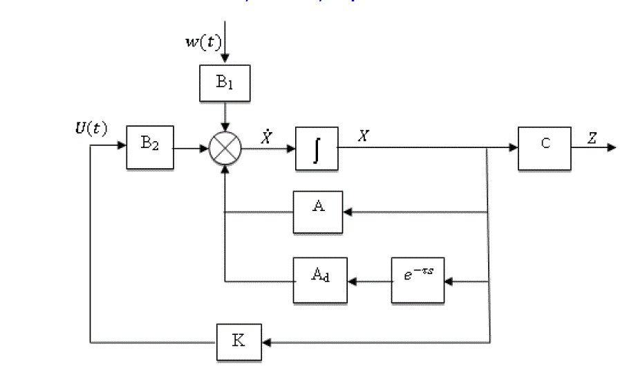
| Consider a continuous linear varying time delay system described by the state equation |
 |
III. DESIGN METHODOLOGY |
First we can find the linear matrix inequality for the system (1) with the control input and the external disturbances as
zeros. Then the state Eqn (1) reduces to a homogeneous system given by |
 |
 |
 |
 |
 |
IV. SIMULATION RESULTS AND DISCUSSION |
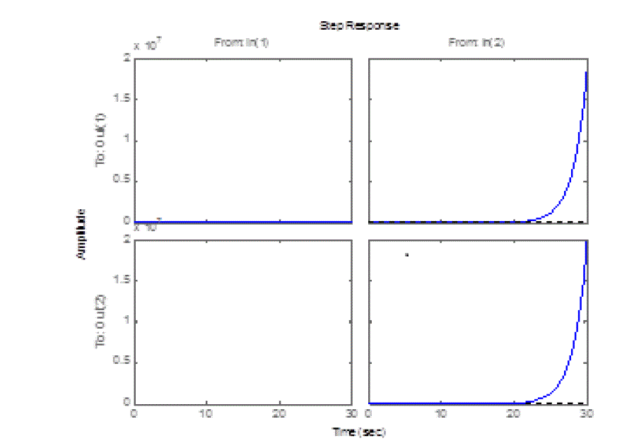
| The controller was synthesized as mentioned above with the help of LMI solvers [15] .Fig 2 shows the open loop
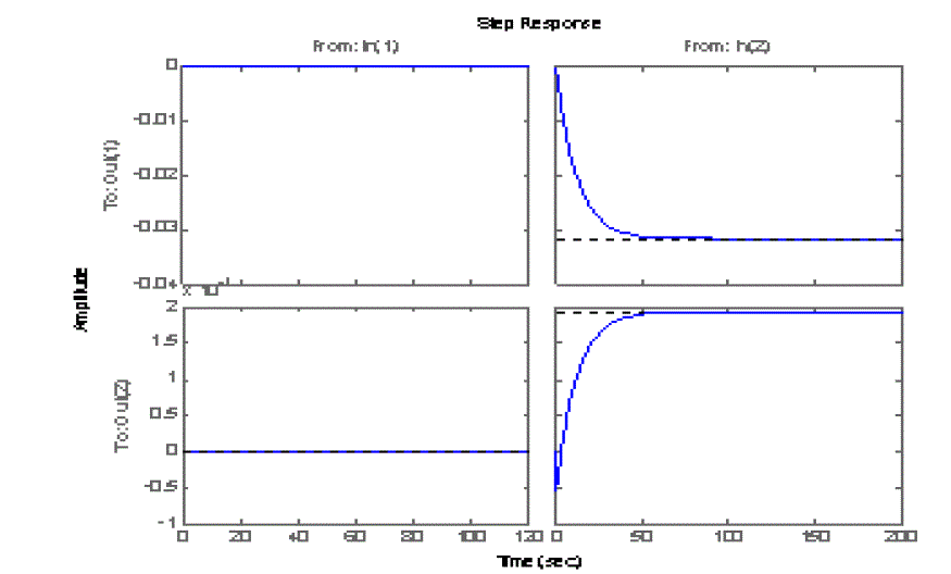
response of the system(1) with time delay 0.1 sec whereas Fig 3 shows the closed loop response of the same system
with same time delay. From these figures it can be seen that the given system is unstable without the controller and is
stable with the proposed LMI controller. From fig 3 it can be seen that when the time delay is 0.1 sec, the settling time
is 47 sec and the steady state errors are -0.0317 & 0.00194 respectively.Then increased the time delay to different
values from 1 sec to 190 sec and found out the corresponding maximum settling time and steady state errors. As in the
previous case here also it can be seen that the system is unstable without the controller and is stable with the controller.
Table 1 gives the Performance specification of the system represented by Eqn(1) with different values of time delay. |
| In Table 1, column (1) shows the time delay. It has been assumed that the time delay would change from 0 to 190 sec
.Column (2) shows the corresponding values of the settling time and column (3) shows the corresponding steady state
error. It can be seen that as the time delay is increased from 1 sec to 10 sec, the settling time is changed from 49.5 sec
to 78 sec but the corresponding steady state errors remains the same. Again it can be seen that when the time delay is
increased to 20 sec and 100 sec, then the corresponding settling time are 114 sec and 428 sec respectively. we can see
that, when the time delay is increased to 160 sec , the settling time is reduced to 204 sec and the steady state error
reduces -0.0281& 0.00125 respectively. From the Table 1 it can be seen that as the time delay increases the settling
time also increases and after a particular delay it decreases. Again we can see that at higher values of delay, the steady
state error becomes zero or approaches to zero. The non-zero error remains constant at large values of delays. |
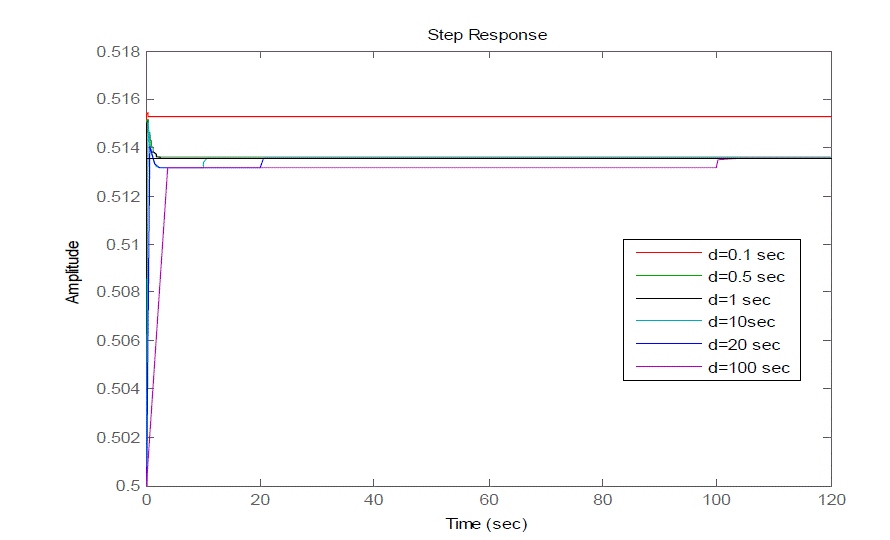
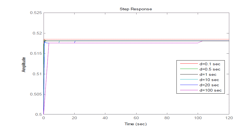
| Fig 4 and Fig 5 shows the closed loop response of the given uncertain system (2) for different values of delay with
disturbance attenuation bound () 1 and 0.5 respectively. It can be seen that as the value of increases the steady state
error decreases but the settling time increases. |
| Fig 4 show the closed loop responses of the given uncertain system having the disturbance attenuation bound 1 with
different delays say 0.1 sec,0.5 sec,1 sec,10 sec,20 sec& 100 sec respectively. From Fig 4 it can be seen that the steady
state error is high for a delay of 0.1 sec whereas it is small for a delay of 100 sec. |
| Fig 5 show the closed loop responses of the given uncertain system having the disturbance attenuation bound 0.5 with
different delays say 0.1 sec,0.5 sec,1 sec,10 sec,20 sec& 100 sec respectively. Here also it can be seen that the steady
state error is high for a delay of 0.1 sec whereas it is small for a delay of 100 sec. Again it can be infer that as the value
of increases the overshoot of the output response also increases. |
CONCLUSION |
| In this paper the LMI control of a linear varying time delay system was discussed. Again a robust ��∞ controller is
developed for linear time delay systems subject to uncertainties in both plant and controller. The robust controller is obtained using an LMI algorithm. The LMI solvers in MATLAB® were made use of for solving the inequalities
[16].The analysis of the system with varying time delay was also performed. In the case of linear varying time delay
system it can be seen that as the time delay increases the settling time also increases. But after a particular delay,
settling time decreases. Again we can see that at higher values of delay, the steady state error becomes zero or
approaches to zero. The non-zero error remains constant at large values of delays. In the case of uncertain time delay
system it can be seen that the steady state error is high for small delay whereas it is small for large delays. Again it can
be infer that as the value of disturbance attenuation bound increases the overshoot of the output response also increases.
The proposed LMI controller would give good performance to systems with uncertainty in time delay. |
Tables at a glance |
 |
| Table 1 |
|
| |
Figures at a glance |
 |
 |
 |
 |
 |
| Figure 1 |
Figure 2 |
Figure 3 |
Figure 4 |
Figure 5 |
|
| |
References |
- Richard J P, âÃâ¬ÃÅTime-delay systems: an overview of some recent advances and open problemsâÃâ¬ÃÂ, Automatica39 pp 1667âÃâ¬Ãâ1694, 2003
- EmillaFridman and Uri Shaked,âÃâ¬ÃÅSpecial issue on time-delay systemsâÃâ¬Ã International Journal of Robust and Nonlinear Control; 13:791-7922003
- Ingimundarson A and HagglundT, âÃâ¬ÃÅPerformance comparison between pid and dead-time compensating controllersâÃâ¬ÃÂ, J. Process Control12 pp887-895 2002.
- Manitius A.Z andOlbrot A.W, âÃâ¬ÃÅFinite spectrum assignment problem for systems with delaysâÃâ¬ÃÂ, IEEE Trans. Autom. Control AC-24pp541-553 1979
- Watanabe K, âÃâ¬ÃÅA process model control for linear systems with delayâÃâ¬ÃÂ, IEEE Trans. Autom. Control AC-26 (6)pp 1261-1268, 1981
- IssamAmri, Dhaousoudani and Mohamed Benrejeb, âÃâ¬ÃÅRobust exponential stabilization of uncertain perturbed systems with multiple timevarying delays in state and control inputâÃâ¬ÃÂ, International Review of Automatic Control pp 191-203, 2011
- Numez-Reyes ,Normey-Rico J. E, Bordons C, and Niculescu, âÃâ¬ÃÅDelay Effects on Stability: A Robust Control ApproachâÃâ¬ÃÂ, Springer-Verlag, Heidelberg, Germany,2001
- Boubertakh H, Tadjine M, Glorennec P Y and .Labiod S, âÃâ¬ÃÅComparison between Fuzzy, PI, PD and PID controllers and Classical PI, PDand PID ControllersâÃâ¬ÃÂ. International Review of Automatic Control pp413-421, 2008
- Han Ho Choi and Myung Jin Chung; âÃâ¬ÃÅAn LMI Approach to H Infinity Controller Design for Linear Time delay SystemsâÃâ¬ÃÂAutomatica,Vol.33,No.4.pp 737-739, 1997
- Wenping Jiang.âÃâ¬ÃÅ Robust H Infinity Controller Design for Wheeled Mobile Robot with Time-delayâÃâ¬ÃÂ. International Conference onIntelligent Computation Technology and Automation.2008
- ShymaMuhammed, and Abraham TMathew Modified smith predictor for the control of unstable non-minimumphase delayed systems,.International Review of Automatic Control pp.531-5382012
- Stephen Boyd, Laurent El Ghaoui, Eric Feron, and VenkataramananBalakrishnan. Linear Matrix Inequalities in System and ControlTheory. Society for Industrial and Applied Mathematics Philadelphia.
- Kim J.H, Lee S.K and Park H.B, âÃâ¬ÃÅRobust and non-fragile H8control of parameter uncertain time-varying delay systems,âÃâ¬Ã inProceedings of the 38th SICE Annual Conference, Morioka, Jpn, pp. 927-93, 1999
- FeiLiu,PeigangJiang,Hongyesu and Jianchu Robust H infinity Control for Time-Delay Systems with Additive Controller UncertaintyProceedings of the 4"' World Congress on Intelligent Control and Automation June 10-14, Shanghai, P.R.China.2002
- Gahinet,P, Nemirovski A, Lamb A.J and Chilali.MLMIControlToolbox: for use withMATLAB. The Mathworks, Inc.Natick, MA, 1995
- www.mathwork.comMatlab Documentation-Control system tool box and Robust control tool box
|