Keywords
|
| Channel modeling, broadband power line communication communications, Multipath, BER. |
INTRODUCTION
|
| BROADBAND OVER POWER LINE COMMUNICATIONS (BPLC) is a term used to identify technologies, set of equipments, applications and software and management services that allow users to communicate over already existing power lines. The advantage of using this technology is that the power-line network is the most pervasive and accessible network. It reaches every power socket in every home. Since the power-line network is already installed, there is no need to lay new cables. The technology operates in the 1-30 MHz and can deliver data rates up to 200Mbps. The logic behind providing high bit-rate data services exploiting the power grid rests in the fact that vast infrastructure already exists in place for power distribution, and hence the penetration of the service could be much higher than any other wire line alternative [1]. |
| To analyze the performance and to access the possibilities of optimization of transmission systems, a reasonably accurate channel model is needed [2]. With this aim, various models of a power-line network for broadband data transmission have been derived in the recent past. Some of those models can be found in Phillips [3], Zimmermann and Dostert [4], and Gali and Banwell [5], etc. However, a widely accepted channel model has not yet been presented, since models based on either experimental results or obtained from specific network topologies or boundary conditions are not general and incomplete, for predicting the behavior of power-line networks. The powerline medium is an unstable transmission channel owing to the variance of impedance caused by variety of appliances that could be connected to the power outlets, and these impedance fluctuations lead to multipath of BPLC channel [4, 6]. The noise present in the BPLC environment makes the communication over power lines further more difficult. |
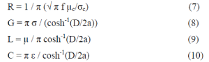
| For the communication engineers, BPLC represents the formidable challenge of transmitting data along a communication media that was originally designed for the electrical energy delivery and not for communication purpose. Since home networking transcends the simply data communication between computers or Internet access, BPLC technology appears as a potential way to become the smart home concept, and the indoor multimedia data interchange, in a reality. Although the performance of BPLC technology supporting multimedia applications with quality service at bit rates of up to 200 Mbps has been proved, it is reasonable to consider BPLC as a complementary technology and not as a competitor for the other home-networking technologies; both wired and wireless [7]. |
II. BPLC CHANNEL MODELING
|
| BPLC channel modeling work can be categorized as BPL communication model, Models of power lines and Source of Interference (Noise) model [2, 8 and 9]. The focus of our work presented in this paper is on the load modeling of indoor BPLC, and in particular, calculation of effects of load on the BER rate. The most representative indoor BPL modeling approaches have been proposed based on the recent literature. Fig 1 shows the block diagram of BPLC channel model. |
| The model can be created by using transmission line theory, which applies chain parameter matrices or scattering parameters to describe the relation between input and output voltage and current by two-port network [2,10,11and 12]. Power line model can also be created by using the concept of environment of multipath signal propagation [4 and 6]. The parameters of this line are obtained from a distribution network topology or based on metering and measurements. |
III. MODELING THE INDOOR POWERLINE BASED ON TRANSMISSION LINE THEORY
|
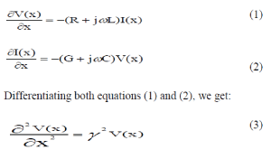
| The indoor power cables (fig.2) are approximated to be a two-wire transmission line with solid core conductor for software simulation. The line voltage V(x) and the current I(x) with x as displacement can be expressed in the frequency domain |
 |
 |
| The propagation of signals over power lines introduces an attenuation, which increases with the length of the line and the frequency. The line attenuation is caused by the heat loss and radiation on the power line and is a function of characteristic impedance Z0 and transmission line complex valued propagation constant γ. These two intrinsic line parameters dominate the wave behavior along the power line. |
 |
| R, L, G and C are the resistance, inductance, conductance and capacitance per unit length of the power line conductor respectively. In order to derive γ and Z0, the four primary line constants have to be derived first. |
 |
| A solution for V (x) and I (x) is: |
|
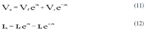 |
| where x is the displacement from the load, negative towards the source, and Vf, Vr, If and Ir are forward and reflected voltages and currents respectively at the load end of the line. The above expressions can be rewritten as: |
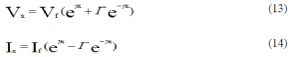 |
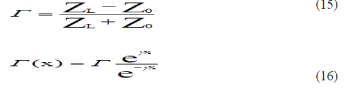
| where Γ is the complex reflection coefficient at the load. Transmission line behavior is described by these equations and the boundary conditions imposed by the load with load impedance given by ZL=V/I. |
 |
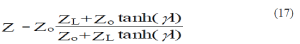
| The equations (1) to (16) fully describe the behavior of a transmission line with a given load impedance. Input impedance Zin of line of length l can be calculated from the load impedance: |
 |
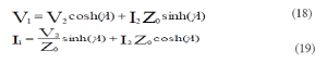
| If V1 and I1 are the voltage and current at the input port, and V2 and I2 are the voltage and current at the output port ; the relationships exist ( equations 18 and 19) for the two port network equivalent of a transmission line: |
 |
| The dielectric material, between the cable conductors, is inhomogeneous in both space (due to the round shape of the cable conductor) and contents (mixture of insulation and air). But since the cables are of close proximity to each other, the thickness „tâÃâ¬ÃŸ of the insulation is comparable with that of the air space between the conductors. In this model, the dielectric is assumed to be just a mixed content material and the effects of the inhomogeneous in space are neglected to keep the model tractable. |
| The simulations have initially been carried out in MATLAB with the small length of transmission line (taken to be 0.01m length) with shunt stub terminated in an open circuit as shown in fig.3a and shunt stub terminated in a short circuit as shown in fig.3b. The simulations have next been carried out in MATLAB with the length of transmission line taken to be 15 m with shunt stub terminated in an open circuit. The simulation results are revealed in fig.4. The length of transmission line is again taken to be 15 m with shunt stub terminated but short circuit. The simulation results are revealed in fig.5. The distance between the two conductors (Live and Neutral) „DâÃâ¬ÃŸ= 2t + 2t + 2a = 4.06 mm |
| t = thickness of insulation = 0.7 mm |
| a = radius of copper conductor = 0.63 mm |
| Conductivity of copper σ C = 5.8 x 10⁷ S/m |
| Relative permittivity of dielectric ε r = 0.8 |
| Conductivity of dielectric σ d = 1 x 10⁻⁵ S/m |
IV. EFFECT OF VARYING LOADS
|
| Low-voltage power distribution networks (indoor) were designed only for supply of electrical signals at 50 Hz to households. The sockets, or terminal nodes, are considered the access points to the channel where transmitter or receiver equipment or loads can be located. Every device connected to the power network represents a load to the network, whose model includes, besides its impedance value, noise source associated with it. The frequency dependent and time variant values of the loads can be obtained directly from measurements of typical electrical loads. Some loads may have constant impedance value as long as their connection status does not change, but others exist that present a cyclic variation of their value according to the mains frequency |
| If a wide range of devices and appliances with variable electrical characteristics are either switched on or off at any location or node and at any time, their variation in the network will lead to strong fluctuations of the impedance. These impedance fluctuations and discontinuity lead to multipath behavior of the BPLC channel, making its utilization for the information transmission more delicate. Model of powerline channel can be expressed as linear combination of a timevarying filter with additive noise and an attenuating multipath channel. The multipath channel with additive noise can be described by an Echo Model [4]. In contrast to the known approaches, a top-down strategy [4] considers the communication channel as a black box and describing its transfer characteristics by a frequency response in the frequency range from 500 kHz up to 20 MHz by very few relevant parameters. The structure of the model is based on fundamental physical effects, which were analyzed during a great number of measurements. However, in contrast to previous approaches, the relevant parameters are not derived from component properties, but from channel measurements |
| The echo model can be described by a discreet time impulse response h (t). |
 |
| Considering the effect of line attenuation due to heat loss and radiation and taking the Fast Fourier Transform, the channel response is given by equation (20). |
 |
| gi is the weighting factor and represents the product of the reflection and transmission factors along the path i |
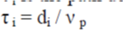
| di is the length of the path. |
| τ i is the path delay introduced by path i and is the ratio of the path length (di) and phase velocity (νp) . |
 |
| The simulation of the BPL system is carried out in MATLAB/SIMULINK with variable number of branches and increasing loads and the BER rate is compared graphically. As observed from fig.8 and fig.9, the effect of changing loads is more on networks with lesser number of branches. With increasing number of branches, the effect of load on the network goes on decreasing. With increase in the number of branches, the impedance of the network decreases because of a large number of impedances in parallel. More the number of branches, lesser is the network impedance. |
V. BROADBAND PLC EQUIPMENTS FOR INDOOR POWER LINE NETWORK
|
| Network performance analysis of CORINEX Communication, Inc. Broadband PLC equipments (fig10 and fig 11) for indoor power line network using measurements of different network characteristics parameters such as throughput and latency is conducted for the network in Jamia Millia Islamia |
| The Corinex AV200 Enterprise Power line Adapters [6, 8 and10] installed enable the users to connect individual PCs or other devices with Ethernet communications links into a local area network through existing electric power lines (Power line), also enable PC file and application sharing, allow peripheral and printer sharing through the Power line network, enables shared broadband Internet access, enables sharing of bandwidth for multimedia payloads, including voice, data, audio and video, eliminates the need for long network cables running throughout. |
VI. CONCLUSION
|
| The simulation results reveal that in a realistic PLC scenario, the transient variations of the nature of termination, value of loads (i.e. transient impulsive noise) and the different network conditions (i.e. different access point with different mismatch), make the PLC transmission channel time-frequency dependent. In principle, channel attenuation depends on the characteristics such as length, per-unit-length parameters, frequency dependence etc. of the cables and of the loads. While the frequency dependence can be mathematically modeled, the load variation cannot be analytically calculated as the loads are applied or disconnected several times a day randomly. The load variations are quite significant. Models of the transfer characteristics of the mains network prove to be significant for design of such future networks. |
Figures at a glance
|
 |
 |
 |
 |
| Figure 1 |
Figure 2 |
Figure 3 |
Figure 4 |
 |
 |
 |
 |
| Figure 5 |
Figure 6 |
Figure 7 |
Figure 8 |
 |
 |
 |
| Figure 9 |
Figure 10 |
Figure 11 |
|
| |
References
|
- S.G. Mallat. A wavelet tour of signal processing. San Diego, CA: Academic, 1998.
- M. Dash, R panda , L Samantaray . “ A Review on Time-frequency , Time-scale and scale-Domain Signal Analysis .” IETE Journal ofResearch , July-August,2005, Vol 51, No 4, pp :287-293.
- Aldroubi and M. Unser. Families of multiresolution and wavelet spaces with optimal properties. Numer. Function. Anal. Optimiz., 14:417-446, 1993.
- Aldroubi and M. Unser. Sampling procedures in function spaces and asymptotic equivalence with shannon’s sampling throry. Numer.Function. Anal. Optimiz., 15:1-21, 1994.
- H.C. Andrews. Computer Techniques in Image Processing. Academic Press , New York, 1970.
- Asker. The spline curve, a smooth interpolating function used in numerical design of shiplines. Nord Tidscar Inform Bechanding, 2:76-82,1962.
- R.E. Barnhill and R.F. Rosenfeld. Computer Aided Geometric Design. Academic Press , New York, 1974.
- J. Haddadnia , K. Faez and M. Ahmadi. An efficient human face recognition system using pseudo zernike moment invariant and radial basisfunction neural network. Int. Journal of Patt. Recog. And Arti. Intell. 17 : 41-62 , 2003.
- X. He et al . Face recognition using laplacian faces. IEEE Patt. Anal. Machine Intell. , 27(3) : 242-249 ,March 2004.
- Liu. Gabor-based kernel PCA with fractional power polynomial models for face recognition. IEEE Trans.Image Processing , 5 : 572-581 , 2004.
- K. Mitra. Digital Signal Processing –a computer based approach. Tata McGraw Hill, 2004.
- M.D. Ortiguera. Introduction to fractional signal processing. Part-I: Continuous-time systems. IEE Proc. On Vision, Image and Signalprocessing, 1:62-70, Feb.2000.
- H. S. Malvar. Lapped transforms for efficient transform/subband cading. IEEE Trans. Accoust. Speech Signal Processing , 38 : 969-978 ,1990.
- Y. Meyer. Wavelets : Algorithms and Applications. Philadelphia, PA: SIAM, 1993.
- R. Panda and B.N. Chatterji. A wavelet decomposition using fast recursive generalised IIR filters. IETE Journal of Research, 47(4):137-139,May-August 2001.
- G. Strang and T. Nguyen. Wavelets and Filter Banks. Wellesley, MA : Wellesley-Cambridge, 1996.
- M. Unser and T. Blu. Wavelet theory demystified. IEEE Trans. Signal Processing, 51(2):470-483, Feb. 2003.
- M. Vetterli and C. Herley. Wavelets and filter banks : Theory and design. IEEE Trans. Signal Processing, 40(9):2207-2232, September 1992.
- G.G. Walter. A sampling theorem for wavelet subspaces IEEE Trans. Information Theory, 38:881-884, 1992.
- R.G. stockwell, L. Mansinha and R.p. Lowe. Localisation of the complex spectrum: The 5 transform. Journ. Assoc. Expl. Geophys. 17:99-114, July 1996.
|