ISSN: 2319-9873
ISSN: 2319-9873
Department of Physics, Faculty of Sciences, University of Yaoundé I, P O Box 812, Cameroon.
Received: 08/07/2014; Revised: 22/07/2014; Accepted: 25/07/2014
Visit for more related articles at Research & Reviews: Journal of Engineering and Technology
The mathematical models of salient-pole high-voltage synchronous generator with brushless excitation system in d, q axis are presented
Mathematical model, brushless synchronous generator, brushless excitation system.
In some modern unified high-voltage automated electro energetic ship systems (UHAEES), we largely use brushless synchronous generators with high-voltage (6.6 kv) and diesel control. In such a synchronous generator (SG) as excitation system we use a synchronous machine with three phase windings in rotor and excitation winding in stator. The voltage at three-phase windings is converted with rotating diode converter and is supplied to excitation winding of SG.
 eq1
eq1
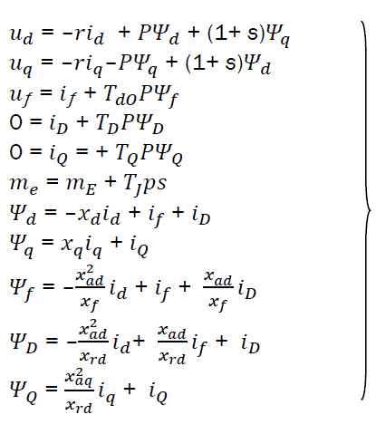
Where ud, uq – stator loop voltages;
id, iq – stator winding currents;
Ψd, Ψq – glowing flux of stator winding
if, Ψf - current and flux of excitation winding
iD, iQ – currents in damper windings;
 - Slip of rotor related to synchronous speed;
mE= Ψdiq + Ψqid – electromagnetic torque of machine;
P = d/dtb - differential symbol with argument tb
r – active resistance of stator winding;
Tdo, TD, TQ – time constants of excitation circuit and damper windings;
 -Motor Inertia Constant
xd,xq - synchronous reactivities of stator;
xad, xaq – reactivities of stator self-induction
xrd, xrq, total reactivities of damper windings;
For a voltage regulation, we use constant voltage electronic impulse regulator which transforms the constant voltage of supply source into a regulated voltage of excitation winding for the synchronous exciter. In such transformations, we use power semiconductors controlled elements IGBT – transistors, while their regulation is done through time-impulse voltage modulation of source supply.
Mathematical model of SG through d and q axesin per units system can be represented with the equation system [1]:
For transformation from per unit representation to physical units, we multiply by basic values. For stator circuit, we use the following basic values:  amplitudes of nominal stator voltage and current;
Ψb= Ub/ωb-flux
Where ωb=ωs=2πƒb-Synchronous angular rotor speed (with ƒb = 50Hz, ωs = 314.16 rad/sec;
Zb =Ub/Ib – resistance;
 - total power;
 -rotating torque;
For winding excitation of SG, we use the following basic values:

For a longitudinal damper loop:

For transversal damper loop:

In equations (eq1) we considered all significant electromagnetic and electromechanical processes in the synchronous machine and in damper winding. Depending on specific particularities of the problem presented, (eq1) can be considerably simplified in their particular part without any great loss to the solution expected.
Concerning the equations, for all the means of automatization of SG, they should be transformed such that, input and output variable currents and voltages could represent corresponding vectors in d and q axes respectively in per units system.
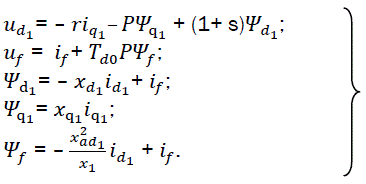
Getting to the mathematical model, describing brushless exciters in rotating coordinates, it is important to note that rotating axes of the machine are attached to the stator and not to the rotor in usual models. Since the coordinate axes of the exciters are not different from the axis of SG, we introduce for them other representations d1, q1. Therefore, the equations of synchronous exciters in per-units form are as follows:

 eq2
eq2
ud1, uq1, uf, id1, iq1,if, Ψd1, Ψq1, Ψf – voltages, currents and flows through longitudinal and transversal axis of armature and winding for exciter respectively;
P – differential symbol;
s – rotor slip of the machine;
Td0 – time constant of exciter circuit;
r, xd1, xq1, xf – winding active and reactive resistances;
xad1 – reactivity of armature self-induction along longitudinal axis;
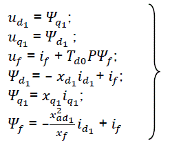
In approximate research related to transient processes in synchronous machines, equations can be simplified by excluding transformers emf in stator loops. If we simultaneously exclude pΨd1, pΨq1 and sΨd1, sΨq1 errors are each other compensated considerably. Further simplification is done by neglecting the active resistance of armature (r =0).
In that case exciter equations will be much simple:
 eq3
eq3
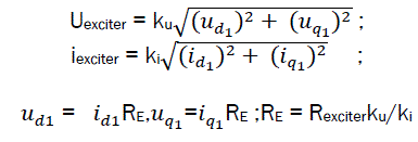
We should also consider the link between exciter armature winding and exciter winding of the machine through rotating converter.
For that purpose, we can replace real load by a certain equivalent resistance RE [2,3,4,5].
Thus,
 eq4
eq4
Where, ku and ki depend on the structure of rotating converter and on parameters of machine excitation windings.
The proposed model of brushless synchronous generator can be used in computer modeling of UHAEES for perspective ships.