Keywords
|
| Model Based Systems Engineering, Metrics, Safety critical embedded systems; Model based tools, Evaluation criteria |
INTRODUCTION
|
| Development of critical systems i.e. the aeronautics or automotive industry requires a strict interdisciplinary approach and conformance to standards and specifications in order to ensure safe systems, since failures are often catastrophic and with loss of life as a consequence. The development of embedded systems with real-time and other critical constraints raises distinctive problems. In particular, development teams have to make very specific architectural choices and handle key non- functional constraints related to, for example, real-time deadlines and platform parameters like energy consumption or memory footprint. Model-Based Design allows engineers to design embedded systems and simulate them on their desktop environment for analysis of the design. This approach helps in detecting the design bugs before implementing on to the target. Model-Based Design provides a variety of code generation capabilities that teams use to generate source code for many purposes including simulation, rapid prototyping and hardware-in-the-loop testing. Model-Based Design promotes a requirements-oriented project view and greater integration and reuse between conceptual and detailed modeling and design work [1][2]. |
| Model-Based Design with automatic code generation is an important and established technology for developing aerospace embedded control systems. Using the model-based approach, one can reduce the risk of mistakes and shorten the development cycle by performing verification and validation testing throughout the development instead of only during the final testing stage. Design evaluations and predictions can be made much more quickly and reliably with a system model as a basis [3]. |
| Model based design methodology encompasses various domains across all phases of design life cycle. In order to support this, there exist various tools that are available for use. These tools are commercially available, while some are open source tools for academic usage and efficiency analysis; others are licensed by tool vendors. Depending upon the level of complexity, functionality and the application domain of the system appropriate tools are used. There are various model based tools that are commercially available and are being used in safety critical domain, particularly for design, analysis and testing purposes. Hence, the selection of appropriate tool contributes in the success of the project. Modern software development tools have direct and growing impact on the effective and efficient development of complex, safety-critical, real-time avionics systems and consequently, on the safety of the flying public. Most of the commercially available tools in the market are volatile and confusing to the buyer, hence selection criteria becomes very important for safety critical systems. The paper proposes, evaluates and discusses the measurement technique used to evaluate the model based tools by generating metrics for their assessment criterion. The technique can be used as a benchmark for the tool selection [4]. |
| The paper is divided into various sections each describing the approach for quantitative assessment of the Model based tools. Section 2 discusses background work and literature survey done in this direction. Section 3 elaborates the proposed measurement technique for various commercially available tools. Section 4 discusses the metrics generated for the tools and demonstrating them using a case study and discusses the outcome of the case study. |
BACKGROUND WORK
|
| Tools [1][5] play an important role in the software engineering process, and the proper selection and use of tools aid those involved in the design and development of real-time systems. On one hand, tools mechanize operations prescribed by methods by storing system representations, transforming representations from one type of model to another, and displaying representations in varying forms. On the other hand, tools empower users by enhancing correctness checking and analytical power, by freeing them from tedious documentation tasks, and by providing multiuser coordination (access and version control). None of these features are easily available in manual method. As development processes, e.g., model-based development (MBD) and automatic code generation (ACG), become more complex, pervasive, and automatic, the need for qualified development tools and related proof of quality for the developed software will increase. There exist lot of commercial software development tools in the market and the proper selection of the tool becomes a challenging task for the buyer. Almost each time a new tool is released, claims are made about its capability for easy interface with other tools. Reality does not match this idealized picture leaving the need for plenty of gluing between the tools artifacts, i.e., in-house work by the developer to get the tools to work together for their application. [6] |
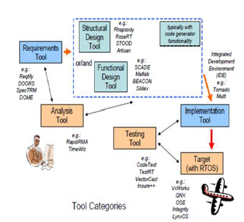
| Desired characteristics of modern tools include multiuser development, shared information repository, integration with third party tools and applications, requirements modeling, executable specifications, use of established software engineering notations, reliable code generation, performance analysis, interface with target for downloading and debugging, and verification and validation of the system. The resulting target code depends heavily on the usability, correctness, and precision of the tools used for the code development; hence the selection of proper tool is necessary. [7]. Fig 1 depicts an example of the tool usage in the various phases of the software development cycle. Tools are classified depending on their application in different phases of the design life cycle i.e Requirements tools, Analysis tools, testing tools, Design tools, Implementation tools and Target tools. Several attempts have been made to create a uniform tool environment to achieve the output of the project [8]. |
PROPOSED MEASUREMENT APPROACH
|
| As the model based systems engineering approach is being widely adopted to design and develop safety critical systems, the need to use appropriate and accurate tool for the purpose becomes necessary. In order to select the most appropriate tool from various existing tools in the market a lot of effort and a standard assessment criterion is required. The proposed approach describes measurement techniques to quantitatively measure the capabilities of a tool so that it becomes easy for the designer to select the most appropriate tool for implementing the application. The effectiveness and applicability of the measurement technique is demonstrated by assessing the tools for a proven indigenously developed Stall warning and Aircraft interface system (SWS/AIC). SWS/AIC system is a safety critical real time embedded system used in aircrafts to warn the pilot of the impeding stall [3]. The stall condition in the aircraft is a critical stage during which the aircraft loses altitude and the pilot will find it difficult to recover when not warned in advance. Hence detection of the impeding stall is very critical. |
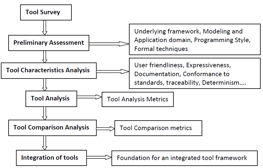
| The approach involves an extensive survey of various commercially available model based tools, study of the tool characteristics, underlying framework, programming and their modeling domain. The tools used for the analysis include Mathworks, SCADE, Reactis, OpenModelica, VisSim, Dymola, Escher and Atego. The preliminary assessment of the tools gives an insight towards the underlying framework on which the tool execution depends, the modeling domain that the tool encompasses and its applicability. The analysis involves detailed study of the tool robustness, determinism, correctness, conformance to standards and correctness of the tool. Tool comparison database is generated as a result of the survey. The proposed approach is depicted in Figure 2. |
| From the analysis, quantitative metrics are obtained by weighted sum methodology for each of the assessment attribute of the tool. The quantitative metrics will provide information about the gaps in the tool which can be overcome by tool integration technique .The approach details the generation of quantitative metrics for each of the analysis attribute described for the tools. The metrics generated as the outcome of the tool analysis are tool analysis metrics and the tool comparison metrics [9][10][11]. |
TOOL ASSESSMENT PROCESS
|
| The main objective of tool evaluation is to define how well the appropriate tool adds value to the project. The preliminary observations done for the tool assessments involve the applicability, functionality, platform dependence and cost effectiveness of the tool. TABLE I depicts the preliminary assessment criterion for the applicable tools that were used in the case study. The analysis was done for MATHWORKS, SCADE, Esterel, Reactis, Escher, VisSim, Atego, Dymola and Open Modelica tools.This analysis was based on the framework, application domain, modeling domain, programming style of the tool and the usage of formal method in the tool. Underlying framework of the tool helps in streamlining the application. Information regarding the modeling domain supported by the tool helps in designing systems for various applications like logic intensive, control intensive or data intensive. Since formal methods (FMs) in the Model-Based Systems Engineering (MBSE) ensures a much safer and more reliable system, tools are analyzed for the formal techniques incorporated in them [12]. |
| The preliminary assessment of the tools is followed by the analysis of the tool characteristics. This gives the developer a level of confidence in tool usage for the application. The characteristics analysis explains the capabilities of the tools and the user interfaces it provides. |
| TABLE II describes the tool characteristics analysis for the model based tools taken into account for the case study.[13][14][15][16][17] |
| The applicability of the tool for a particular application is determined by the tool analysis and comparison metrics. The metrics considers the static and the dynamic behavior of the tool for a proven safety critical system: Stall warning and aircraft interface computer system. The following sub sections describe the tool analysis metrics and the tool comparison metrics generated for the tools used for implementation of the case study. [18][19][20] |
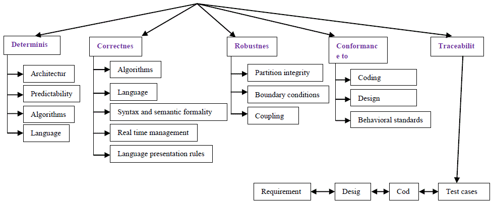
| The tool analysis while implementing depends on the impact it has on the system during the process. The different tool attributes that are analyzed are: |
| • Determinism |
| • Robustness |
| • Traceability |
| • Correctness |
| • Conformance to standards |
| Determinism—the transformation does not introduce uncertainty in the output: the same model input always results in the same output. The attributes that define the determinism of a tool are architectural, predictability, algorithmic and lingual. |
| Robustness—the tool shall be able to handle incorrect inputs and recover from the error; a failure of one component does not propagate to others (a designated degradation mode is desirable in a safety-critical system). Robustness of a tool depends on the partition integrity, boundary conditions and coupling. |
| Traceability—the input and output sets is a bijection: each component of the code can be traced to the model element (and vice versa). The tool must have the tracing feature right from requirements to test cases. |
| Correctness—the transformation retains the original semantic meaning of the input (graphic representation or its internal format), thus the resulting outputs (generated code) are the exact representation of the graphic constructs supported by the tool. Correctness of the tool depends on its ability to provide correct algorithms, language, real time management, formality and presentation. |
| Conformance to standards—the tool uses appropriate notations to describe the product architecture and design whenever one or more standards are applicable (e.g., UML, control-flow diagrams). Also, the generated source codes are created in compliance to any applicable rules (such as complexity restriction) and the coding standards. Conformance to coding standards, design standards and behavioral standards is analyzed. . [21][22] |
| The tool attributes are depicted in Fig 3. TABLE III depicts the analysis metrics generated for the set of tools used for SWS/AIC system as a case study. The metrics are obtained by calculating the weighted sum of the attributes discussed above. |
| From the tool analysis, it is observed that most of the commercially available model based tools have a Matlab/Simulink gateway. The Simulink gateway allows import and export of data/models /signals from and to the tool depending on the requirement. Many tools have a limited link to the Simulink library; hence Simulink library can be treated as universal set for developing model based designs. It is also observed that many tools use formal verification techniques for verifying the models. The most widely used formal verification engine is the Prover Engine which has plug-ins for many tools including Matlab, SCADE, Rhapsody, Statemate etc. The qualitative attributes of the tools are compared and quantitative metrics are generated for the same. The tool comparison metrics helped in computing the tool attributes, compatibility of tools with each other to integrate the tools for enhancing the overall attribute of the engineering process to be adopted for a application. The integration of the tools leads for an efficient framework. TABLE IV describes the tool comparison metrics for the tools. [23] |
| From the tool comparison metrics, quantitative measurement of the abilities of the tools is done. The gaps of the tools are bridged by integrating it with other tool of same intended application. Fig 4 describes the attributes for which the weighted sum approach is used in order to generate the metrics. [24] |
CONCLUSION AND FUTURE SCOPE
|
| The proposed measurement technique provides the benchmark to evaluate tools to be used in the project. The case study for the proven system provides the approach to compute the metrics, evaluate the metrics and select the appropriate tool for the program based on the functionality, schedule, budget and safety requirements. The results provided a basis for determination of tool quality and its usage in the future projects. |
| The metrics generated for the tools helped in analyzing the gap for the tools for the particular application. The compatibility of the tools provides alternatives for filling these gaps for a particular application. The gaps found during the tool analysis can be overcome by tool integration method. The case study has helped in directing the work towards developing an integrated tool platform consisting of various model based tools for enhancing the efficiency of the process at different phases of the design life cycle. |
ACKNOWLEDGEMENTS
|
| The authors wish to thank Director, CSIR-NAL in supporting us in carrying out this research work for improving the engineering process. |
Tables at a glance
|
 |
 |
 |
 |
| Table 1 |
Table 2 |
Table 3 |
Table 4 |
|
Figures at a glance
|
 |
 |
 |
 |
| Figure 1 |
Figure 2 |
Figure 3 |
Figure 4 |
|
References
|
- David W. Oliver, “A Systems Engineering Tool Taxonomy”, Model Based Systems Inc.
- Manju Nanda and Chinmayi S Jamadagni, “Quantitative Metrics for Validating the Effectiveness of Model Based Approach forIndigenously Developed SWS/AIC System”, International Journal of Scientific and Industrial Research, Vol 3, Issue 9, Sept 2012,ISSN 2229-5518
- “Measuring productivity and quality in model based design”: excerpt from MATLAB digest; March 2006
- “Model Based Design for DO178B with qualified tools” by Tom Errkinen and Bill Potter; Mathworks Inc.
- “Comparison of software metrics tools” by RüdigerLincke, Jonas Lundberg and WelfLöwe. Software Technology Group, School ofMathematics and Systems Engineering, Växjö University, Sweden.
- Certification Authorities Software Team (CAST) Paper 1, “Guidance for Assessing the Software Aspects of Product Service Historyof Airborne Systems and Equipment,” June 1998
- Andrew J Kornecki, Nick Brixius, JanuszZalewski Herman Lau, Jean PhillipeLinardon, Jonathan Labbe, Darryl Hearn, KimberleyHall, Lazar Crawford, Celine Sanouillet and Mathieu Milesi, “Assessment of Software Development tools for safety critical , r ealtime systems”, DOT/FAA/AR-06/36, July 2007.
- Manju Nanda, J Jayanthi, Chinmayi S Jamadagni and Madhan V, “Quantitative Metrics For Evaluating Tools To Develop AnIntegrated Tool Platform For Critical Systems”, IEEE Syscon 2013.
- Grove, R.A. and Heizman, J.L., “Safety Criteria and Model for Mission-Critical Embedded Software Systems,” IEEE Software Magazine,CH3033-8/91/0000-0069, 1991.
- Rushby, J., “Formal Specification and Verification for Critical Systems: Tools, Achievement and Prospects,” EPRI TR-100294, Vol. 9, January1992, pp. 1-14.
- IEEE Std. 1061-1998, “Software Quality Metrics Methodology,” IEEE, New York, December 1998
- “A report on analysis of model based systems engineering using formal methods”, NAL PD 1231, Nov 2012
- www.mathworks.com, dated 02/09/2013
- www.esterel-technologies.com, dated 02/09/2013
- www.vissim.com, dated 02/09/2013
- www.dymola.com, dated 02/09/2013
- www.openmodelica.org, dated 02/09/2013
- “A Guide to the Classification and Assessment of Software Engineering Tools”, Technical ReportCMU/SEI-87-TR-10, ESD-TR-87-111, August1987.
- IEEE Std. 982.1-1988, “Standard Dictionary of Measures to Produce Reliable Software,” IEEE, New York, September 1988.
- IEEE Std. 982.2-1988, “Guide for the Use of IEEE Standard Dictionary of Measures to Produce Reliable Software,” IEEE, New York,September 1988.
- “A new approach to system reliability” by GopalChaudhri, Kuolong Hu and Nader Afshar. (IEEE transactions on Reliability: March 2001)
- “Quantifying the analyzability of Software Architectures” by Eric Bouwers, Jos´e Pedro Correia, Arie van Deursen and JoostVisser (DelftUniversity of technology ,Delft , Netherlands)
- “Information Technology – Software Product Evaluation – Quality Characteristics and Guidelines for Their Use,” ISO/IEC 9126, Geneva,Switzerland, 1991
- Abel, D.E. and Rout, T.P., “Defining and Specifying the Quality Attributes of Software Products,” The Australian Computer Journal, Vol. 25,No. 3, 1993, pp. 105-112
|