Keywords
|
| stepper motor, positioning, belt driven mechanism, timing pulley and accuracy. |
INTRODUCTION
|
| Though there are several models for plotter, this plotter is designed in economical way. Main advantage of this plotter is we can replace the tool based on any application such as engraving machine, laser cutting machine, painting any surface and drawing purposes. |
| In this paper, ultra low power microcontroller of MSP430 is used which consumes only 3.5v as input. Moreover, in several plotter design manufacturers use Pulse Width Modulation based driver circuit which has in-built timer circuit in it which makes the user easy. But, when the user tries to modify the timer, they feel difficult to modify as they wish. So, it is better to use separate timer circuit which is available in microcontroller. |
II. IMPLEMENTATION
|
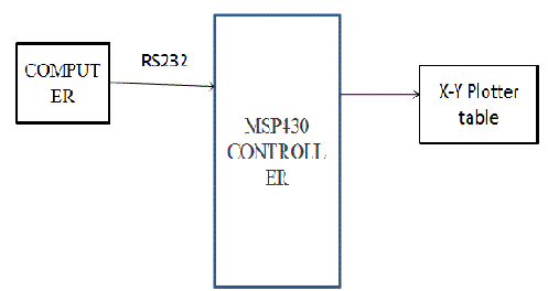
| From figure 2, we describe the hardware and software implementation for this paper. |
HARDWARE DESIGN:
|
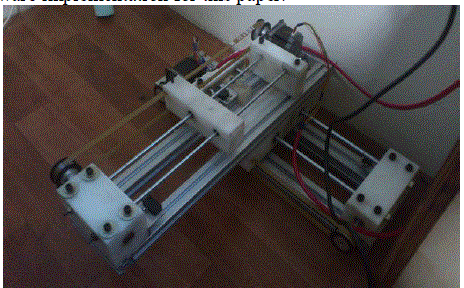
| Main components of hardware design are stepper motor, guiding shaft, limit switch, aluminium profile, PU belt, pulley, bearing, connecting wires, nylon block and MSP430 microcontroller. |
| A. Stepper motor : |
| Most of the application runs on servo motor, but accuracy cannot be maintained. So to maintain better accuracy stepper motor is chosen. There several types of stepper motor: they are hybrid synchronous stepper, variable reluctance stepper, permanent magnet stepper. Main two models are unipolar and bipolar stepper motor. In this paper, 6-wire unipolar hybrid synchronous motor of 1.8 degree step angle is used for better positioning and accuracy. |
| Functioning of motor is based on stepping action. There are several stepping modes. They are full step, half step, micro step. Normally the sequence for motor is A+ A- B+ B- . |
| Main consideration of stepper motor is torque and power rating. Based on the torque, load can be used for driving. Two stepper motor is used for x-axis and y-axis movement and their torque is 5kg/cm and 10kg/cm |
| B. Guiding shaft : |
| For the movement of solid block structure to move along its path without any shake, guide rod is used. Based on load, material of the guide rod is chosen. There are several materials such as mild steel, EN8, EN19, EN24, aluminium. Mild steel cannot withstand heavy load whereas EN8 and EN24 can withstand heavy load.EN8 material is used here. |
| C. Limit switch : |
| It is a switch operated by the motion of a machine part or presence of an object. They are used for control of a machine, as safety interlocks, or to count objects passing a point. It is an electromechanical device that consists of an actuator mechanically linked to a set of contacts. When an object comes into contact with the actuator, the device operates the contacts to make or break an electrical connection. |
| D. Aluminium Profile : |
| Aluminium is preferred than iron due its rust free nature and good conductivity as well as best heat sink. Based on the manufacturer profile size may vary. Example sizes are 30x30, 40x40 square profile. |
| E. Poly Urethane belt : |
| There are several types of belt made of different material. In this paper, timing belt is used because of its accuracy and positioning. Timing belts are available in rubber, fiber re-in forced in rubber and Poly Urethane material with different circumference sizes such as 550mm, 1100mm are available. If application is based on the oil and water, then poly urethane belt is preferred. If the application is based on the open environment, then fiber re-inforced belt is preffferd. In this paper, belt specification is 1100mm circumference, 5mm pitch (T5), width of 9mm is used. |
| F. Pulley: |
| Pulley can be made with different type of material such as plastics, steel, aluminium and nylon block. As compared to other material aluminium gives long life. Pulley parameters are hub, pitch, flange, key lock, inner diameter and outer diameter. |
| G. Bearing: |
| In this paper, linear and ball bearing are used. linear bearing is used for linear movement in guiding shaft and ball bearing is used for rotational movement in free end pulley support. Based on the outer diameter of guiding shaft, both linear and ball bearing are chosen. Care must be taken that outer diameter of guiding shaft must be equal to inner diameter of bearing. |
| H. Nylon block: |
| Since it is one time machine design, cost is one of the main factors. So, it is best alternative of mild steel material. Drilling can be done in lathe or milling machine. While drilling the through hole for inserting linear bearing, through hole must be greater inner diameter of the linear bearing. |
| I. Microcontroller: |
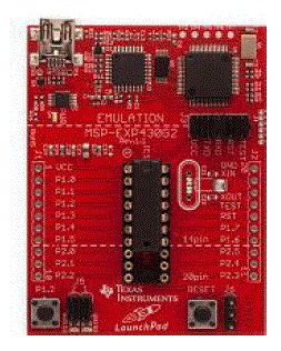
| To use the microcontroller pins effectively, best controller must be chosen. From figure 3 represents MSP430G2 launch pad is used with controller family number MSP430G2553 of 20 pin in it. It is ultra-low power microcontroller of 3.5v with inbuilt UART, UCSI in the launch pad. This microcontroller is of Texas Instruments manufacturer. |
| SOFTWARE USED: |
| MATLAB, IAR Embedded workbench, multisim, proteus, solidworks are the several software used for this project. |
| A. MATLAB: |
| Using MATLAB, you can analyze data, develop algorithms, and create models and applications. The language, tools, and built-in math functions enable you to explore multiple approaches and reach a solution faster than with spreadsheets or traditional programming languages, such as C/C++ or Java. Input signals are generated in MATLAB and given to microcontroller through UART. Input signals can be periodic signals, aperiodic or random signals based on the x and y co-ordinates given by the user. |
| B. IAR Embedded workbench: |
| IAR Embedded Workbench is a development environment that includes a C/C++ compiler and debugger that supports 30 different processor families. C and C++ compilers, debuggers, and other tools for developing for 8-, 16-, and 32-bit processors. Programs are written in C language. |
| C. Proteus: |
| Proteus is software for microprocessor simulation, schematic capture, and printed circuit board (PCB) design. Stepper motor driver circuit design and power supply design also done in proteus software. |
| D. Solidworks: |
| SolidWorks is a 3D mechanical CAD (computer-aided design). Before purchasing material for the project, diagram containing correct dimension should be drawn and simulated in this software. This avoids the wastage of the material and saves money. Figure 4 shows the complete solidworks simulation model. |
III. RESULTS AND TABLES
|
| A. Pulley calculation: |
| Based on the timing belt pitch and gear ratio, timing pulley is designed with appropriate outer and inner diameter. In this paper, 5mm pitch belt is used and 10mm belt width is used. |
| Consider the outer diameter of pulley is 40mm. |
| Circumference= π x diameter |
| = π x 40mm= 125.663 mm |
| Number of teeth = circumference / pitch |
| = 125.663/ 5 = 25.13 |
| So, round-off the value 25.13 teeth to 26 teeth. |
| From the table 1, for belt width 10mm various sizes of pulleys are available. |
| B. MATLAB ouput: |
| Based on the user input, whether periodic or aperiodic signals to be generated. From the generated co-ordinates, points are plotted. |
| From figure 6, the square wave co-ordinates are generated and sent to microcontroller via UART. |
IV. CONCLUSION
|
| From this paper, we can generate several application based on x and y axis movement. Instead of pen, we can insert laser tool for cutting purposes. Moreover, this paper can be modified into three axis movement. |
| |
Tables at a glance
|
 |
| Table 1 |
|
| |
Figures at a glance
|
 |
 |
 |
| Figure 1 |
Figure 2 |
Figure 3 |
 |
 |
 |
| Figure 4 |
Figure 5 |
Figure 6 |
|
| |
References
|
- Martin, J. D., 'Frequency scaling by digital means', IEEConference on Digital Instrumentation 1973, pp. 67-73. (IEE ConferencePublication No. 106).
- Bresenham, J. E., 'Algorithm for computer control of a digitalplotter', IBM Systems J., 4, no. 1, pp. 25-30, 1965.
- Brunetti, G. et al, 'A new family of intelligent multi-color xyplotters', Hewlett-Packard J., 29, no. 2, pp. 2-13, September 1977.
- Dalzell D.T..,’ An economical intelligent plotter’, ,Institution of Electronic and Radio Engineer, Vol. 48. No. 11. pp. 573-579,November 1978
- J. E. Bresenham "Algorithm for computer control of a digitalplotter", IBM Syst. J., vol. 4, no. 1, pp.25 -30 1965
- V. V. Athani and S. B. Kurbet "Digital X-Y plotter", Proc.AICA, 1970
- T. R. Fredriksen "Stepping motors come ofage", Electrotechnology, vol. 80, pp.36 -41 1967
- V. V. Athani and N. Rajagopal "Closed loop step servosystems", J. Inst. Telecommun. Eng., vol. 15, no. 6, pp.445 -453 1969
- Dinesh P. Mital, Chin Teck Chai and Toe Myint, "A PrecisionStepper Motor Controller for Robotic Applications,"89CH2792-0/89/0000-0656, 1989 IEEE, pp. 686-691.
- Hoang Le-Huy, Patrice Brunelle and Gilbert Sybille, "Designand Implementation of a Versatile Stepper Motor Model For Simulink'sSimPowerSystems," 978-1-4244-1666-0/08, 2008 IEEE, pp. 437-442
- J. D. Leon-Morales, R. C. Linares, and O. H. Geuvara,"Observer based controller for position regulation of stepping motor," IEEProc. Control Theory Appl., vol. 152, No. 4, pp. 467-476, July 2005.
|