Keywords
|
| antenna array, mutual coupling, reflection coefficient, transmission coefficient. |
INTRODUCTION
|
| We can always use a high dielectric constant substrate to reduce the EBG cell size. The price we pay is the narrow bandwidth. This effect is similar to a microstrip patch antenna design. |
| An important feature in the uni-planar EBG design is the removal of vertical vias. Thus, it simplifies the fabrication process and is compatible with microwave and millimeter wave circuits.[5] The operational mechanism of the uniplanar EBG surface can be explained by the lumped LC model. The capacitance C also comes from the edge coupling between adjacent patches. Instead of using vertical vias to provide an inductance L, a thin microstrip line on the same layer of the patches is used to connect them together. Thus, this structure is named as a “uni-planar” EBG. To increase the inductance value, the microstrip line needs to be inset into the patch. In the case of the uni-planar EBG surface, it has no vertical vias, which makes the fabrication easier. In addition, it is less sensitive to the incident angle and polarization. |
| The aforementioned EBG surfaces consist of symmetric square units. Thus, the reflection phase for a normally incident plane wave is independent of its polarization state. It is an isotropic structure for normal incidence. Selecting a type of 2 dimensional EBG depends on physical structure and bandwidth of operation. |
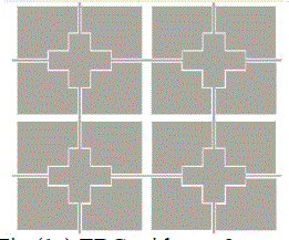
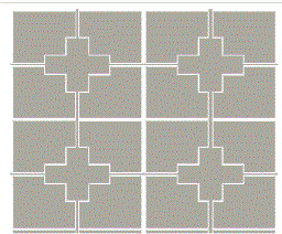
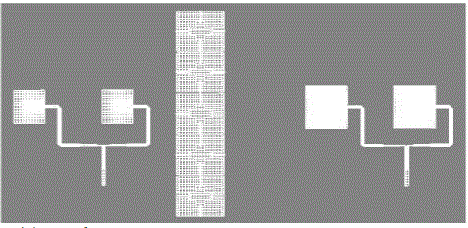
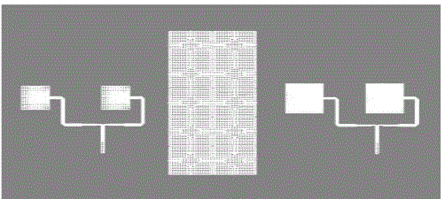
| The gap width g controls the coupling between EBG patch units (refer fig.1). Hence, variation of the gap width also affects the frequency band of the EBG surface. During this investigation, the patch width, substrate permittivity, and substrate thickness are kept the same. It is noticed that the variation in the gap width has the opposite effect to the patch width. When the gap width is increased, the resonant frequency increases. Meanwhile, the slope of the curve becomes flat near the resonance, which indicates a wide bandwidth. According to the lumped LC model, increasing the gap width will decrease the value of the capacitance C. Thus, both the resonant frequency and the bandwidth increases. The EBG structure, with change in gap, are shown below. |
| Changing the gap from 1mm to 2mm; results are found to be varying. |
II. SIMULATION RESULTS
|
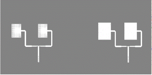
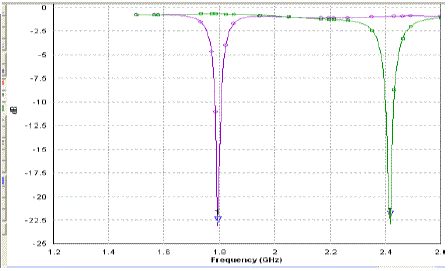
| The arrays designed are placed on same substrate of permittivity of 4.3. The reflection coefficients S11 and S22 are found to be -22.7dB for 1.8GHz array and -22.2dB for 2.4GHz array. The gap between the two arrays will decide the reflection. If the gap is reduced the reflection will increase. Thus more signal power is lost. |
| The VSWR are found to be 1.16 and 1.23 respectively for 1.8GHz and 2.4GHz array. The transmission coefficients are found to be -61.6dB and -61dB for 1.8GHz and 2.4GHz array respectively. Including EBG will have major impact on this and thus on antenna gain. |
B. Antenna arrays with EBG with gap 1mm
|
| No much change in radiation pattern is seen. But the rise in radiation and antenna efficiency is seen for the gap of 2mm. There is rise in antenna gain as well. The bandwidth approximately calculated from the radiation characteristics observed in more than the bandwidth got for arrays without EBG. Increasing gap increases the bandwidth. |
| Fall in transmission coefficient in 2mm gap as compared to gap of 1mm is seen. Beam width decreases as the gap is increased in case of EBG with 1 column stack. As the number of columns are increased the bandwidth increases but there is reduction in the antenna gain. |
| Table1provides the array parameters for EBG with only one column of EBG structure stack. It records increase in radiation efficiency as well as antenna efficiency for array of 2.4GHz but no change at 1.8GHz. This very well indicates that the lowest resonant frequency in the set of array is now not getting coupled to other array, thus improving its performance. It also increases the antenna gain. |
C. Antenna arrays with EBG with gap 2mm
|
| No much change in radiation pattern is seen. But the rise in radiation and antenna efficiency is seen for the gap of 2mm. There is rise in antenna gain as well. The bandwidth approximately calculated from the radiation characteristics observed in more than the bandwidth got for arrays without EBG. Increasing gap increases the bandwidth. |
| Table2 above shows that there is improvement in bandwidth as well as reflection coefficients. Increasing the gap increases the bandwidth. Inserting EBG between the arrays operating at 1.8GHz and 2.4GHz is not reducing the reflection coefficient much but it reduces the transmission coefficients very well. It improves the antenna gain operating at 2.4GHz by 0.91dB in this case. The directivity is further increased by 0.9dBi. The radiation efficiency is getting reduced because of addition of EBG. Beam width is reducing as the gap is increased from 1mm to 2mm. |
RESULTS
|
| By changing the gap from 1mm to 2mm shows effect over the bandwidth. The bandwidth increases by 10MHz keeping antenna gain as well as directivity much higher. The antenna gain is 5.29dBi for EBG with gap of 2mm as compared to 4.75dBi for gap of 1mm in case of one column structure. Rise of 8.5dB is seen in S12 at gap of 2mm as compared to gap of 1mm. Directivity increases by 0.8dB. Beamwidth increases by 2°. Antenna gain at 2.4GHz is not much increased with two column structure but the bandwidth increases by approximately 10MHz at 1.8GHz and at 2.4GHz. The actual frequencies of resonance are observed to be 1.789GHz and 2.402GHz respectively as compared to the frequencies of 1.8GHz and 2.4GHz for individual arrays after optimization. The shift is observed when the arrays are placed on same substrate. Using uniplanar EBG this shift is not much affected. Uniplanar EBGs do not show wide variations in the antenna parameters like reflection coefficient, radiation pattern. In the work done here it shows better transmission coefficients along with rise in antenna gain. |
IV.CONCLUSION
|
| The design of EBG structure is done to the lowest cut off frequency. In this case, the frequency to be suppressed from coupling is 1.8GHz. The arrangement used is inline arrangement for placing antenna arrays. Interfering signals are that of 1.8GHz array that affects the performance of 2.4GHz array. |
| Gain of the 2.4 GHz arrays is improved by 15.3 % in case of 1mm gap and bandwidths by 14.3% in case of 2mm gap at the cost of drop in gain. But still the gain is improved by 1%. These results are seen with uniplanar design as compared to complicated multilayer or different substrate designs. |
| |
Tables at a glance
|
 |
 |
| Table 1 |
Table 2 |
|
Figures at a glance
|
 |
 |
 |
 |
| Figure 1a |
Figure 1b |
Figure 2 |
Figure 3 |
 |
 |
 |
| Figure 4 |
Figure 4a |
Figure 5 |
|
| |
References
|
- Jing Liang and Hung-Yu David Yang “Radiation Characteristics of a Microstrip Patch Over an Electromagnetic Band gap Surface”, IEEEtransactions on antennas and propagation, vol. 55, no. 6,1691-1697, June 2007
- Q. Lin, J. Liang, Y.-S. Zeng, and H.-M. Zhang, “ A novel compact and wide-band uni-planar Ebg structure”, P. R. China Progress InElectromagnetics Research C, Vol. 1, 37–43, 2008
- Fan Yang and YahyaRahmat-Samii “Microstrip Antennas Integrated With Electromagnetic Band-Gap (EBG) Structures: A Low MutualCoupling Design for Array Applications”, IEEE transactions on antennas and propagation, vol. 51, no. 10, 2936-2946, October 2003
- Stylianos D. Assimonis, Traianos V. Yioultsis and Christos S. Antonopoulos, “Design and Optimization of Uniplanar EBG Structures for LowProfile Antenna Applications and Mutual Coupling Reduction”, submitted to IEEE transactions.
- Fan yang, , Yahyarahmat-samii,” Electromagnetic Band Gap Structures in Antenna Engineering”, Cambridge University Press 2009
|