Keywords
|
| BLDCMOTOR, PWM Technique, MATLAB/SIMULINK |
| |
| |
INTRODUCTION
|
| The torque ripple of this conventional method is highly generated because during commutation intervals the motor current naturally flows through the freewheeling diodes [1]. In literatures, the minimization of torque ripple could be accomplished by debus voltage control method. However, the additional dc link voltage control circuits are required, increasing overall cost[2]-[3]. Another method of torque ripple reduction is current control method. The method is based on a strategy in which the current slopes of incoming and outgoing phases during commutation intervals can be equalized by proper duty ratio control [4]. However, this method also requires the current sensors, increasing overall cost. In [5], the wide angle control method of reducing torque ripple by means of driving thequasi-sinusoidal current was proposed. |
| Their results showed that torque ripple in sinusoidal current drive is better than square drive control. Unfortunately, the phase current is delayed in high speed range due to the winding dynamics and back EMF. In this paper, the PWM technique is therefore proposed to minimize the torque ripple and designed to overcome the disadvantages from other torque ripple reduction methods. Adjustment of duty cycle during commutation intervalscanminimize the torque ripple. The incoming and outgoing phase currents are properly shaped such that the resulting phase current ripple is minimized during commutation intervals. Moreover, only terminal phase voltages are measured for calculating the commutation interval time. In addition, the fewer number of devices is used with less computation. Consequently, this proposed method is suitable to the low-cost applications. |
II.ANALYSIS OF TORQUE RIPPLE DURING COMMUTATION INTERVAL TIMEYSTEM
|
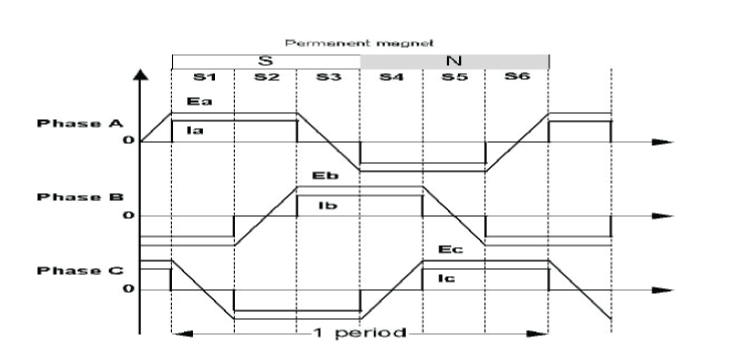
| Theoretically, the BLDC motor produces the trapezoidal back-EMF waveform and the waveform of the excited phase current is quasi square shape as shown in Fig. 1. The three phase voltage equations can be expressed in equation (1) [1] van , vbn , vcn are the phase voltages of stator windings; ia , ib , ic are the phase currents of stator windings; a , Eb , Ec are the phase back EMFs;m is the mechanical angular velocity of BLDC motor;Te is the electromagnetic torque; |
 |
| Electromagnetic torque can be found by equation (2). |
 |
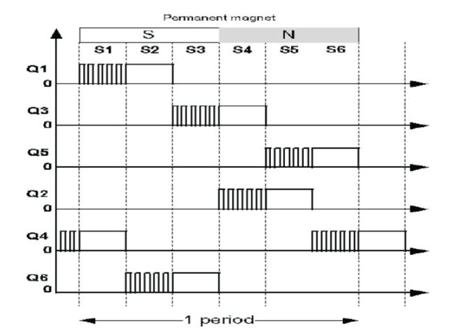
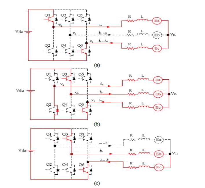
| Fig. 2 shows the switching pattern of conventional PWM-ON technique, consisting of six stages (S1, S2, … and S6). The upper IGBT switches of phase-a, -b, and -c (Q1, Q3, and Q5) are shopped in one-sixth of fundamental period before the following 60ο electrical degrees these switches are always turned on. For the lower IGBT switches of phasea, b, and c (Q2, Q4, and Q6), they are similarly operated as the upper IGBT switches. In each phase, the upper and lower IGBT switches are operated with phase difference of 180ο electrical degrees.Fig. 3 illustrates the commutations of the phase currents from phase-a to phase-b between stages S2 and S3. The current flowing is mainly performed by switching-off Q1 and switching-on Q3. In reality, the phase current does not immediately commute. The freewheeling diode of Q2 will provide the current path during this commutation interval until the phase-a current reduces to zero as seen in Fig. 3 (b).Finally, the phase-b current would flow through switches Q3 and Q6 in the stage S3 as show in Fig. 3 (c). |
III.PROPOSED PWM TECHNIQUE MINIMIZING TORQUE RIPPLE
|
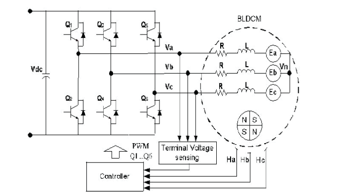
| Fig. 5 shows the configuration circuits of inverter and BLDC motor drive system. The rotor position is detected by Hall sensors (Ha, Hb, and Hc). The upper IGBT switches (Q1, Q3, and Q5) and lower IGBT switches (Q2, Q4, and Q6) are operated in PWM-ON technique. Three terminal phase voltages are measured in the system using differential amplifiers. The commutation interval time can be directly determined by these measured terminal phase voltage signals as shown in Fig. 6. Next subsection will explain the determination of commutation inverter time. |
| A. Determination of commutation interval time |
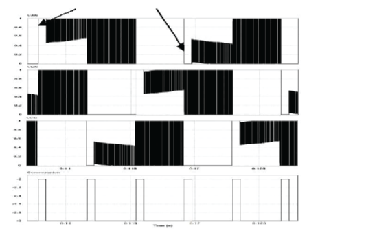
| The proposed method primarily determines the commutation interval time based on measured three terminal phase voltages (Van, Vbn, and Vcn). When considering the terminal phase-a voltage, two commutation points can be detected as shown in Fig. 6. In case of rising edge the terminal voltage of floating phase, the commutation interval occurred before the terminal voltage is floating. Terminal phase voltage during the commutation time is equal to dc bus voltage. On the other hands, in the case of falling edge the terminal voltage of floating phase, the commutation interval occurred before the terminal voltage is floating. However, terminal phase voltage during the commutation time is equal to zero voltage. Finally, the determination of commutation interval time in every stage is summarized in Table I. |
| B. Proposed PWM technique |
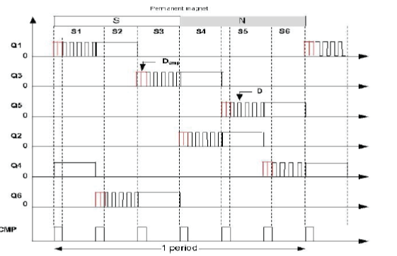
| In Fig. 7, the switching pattern of proposed PWM technique is shown. As seen, six additional commutation intervals are inserted between 60 electrical degrees. To minimize torque and current ripples, the duty cycle is optimally calculated during commutation intervals. Referring to equation (6), the duty cycle during commutation interval time can be represented as follows [10]. |
 |
| where D and Dcmp are duty cycle during non-commutation and duty cycle during commutation, respectively |
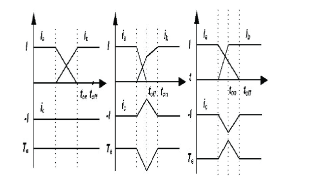
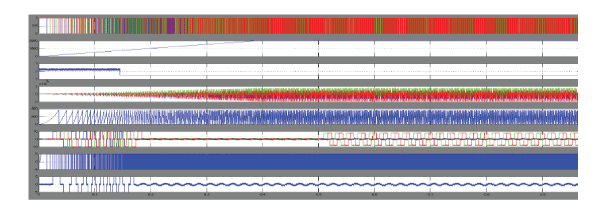
| Fig9. shows the simulated waveforms of phase currents commutation intervals and PWM signals of Q3 and Q6 in case of the conventional PWM-ON technique previously presented in Fig. 2. In this simulation, the motor speed is 2,000 rpm. In Fig. 9(b), it is clearly that the decaying rate of phase-a current and the rising rate of phase-b current are not equal to each other. Therefore, the phase-c current has ripple. Fig. 9(c) shows the PWM signals of Q3 during current commutation from phase-a to phase-b without adjusting the duty cycle. Next, the same overall block diagram of BLDC motor drive with the same speed condition of 2,000 rpm is tested with the proposed PWM-ON technique. Fig. 10 shows the simulated waveforms of phase currents commutation intervals and PWM signals of Q3 and Q6 in case of the proposed PWM technique shown in Fig. 7. As expected, the major improvement of current ripple can be observed in Fig. 9(a). In Fig. 9(b), the decaying rate of phase-a current and the rising rate of phase-b current are equal to each other, resulting in the smooth phase-c current without ripple. The PWM signals of Q3 during current commutation from phase-a to phase-b with adjusting the duty cycle can be seen in Fig. 9(c). |
VI. SIMULATION RESULT
|
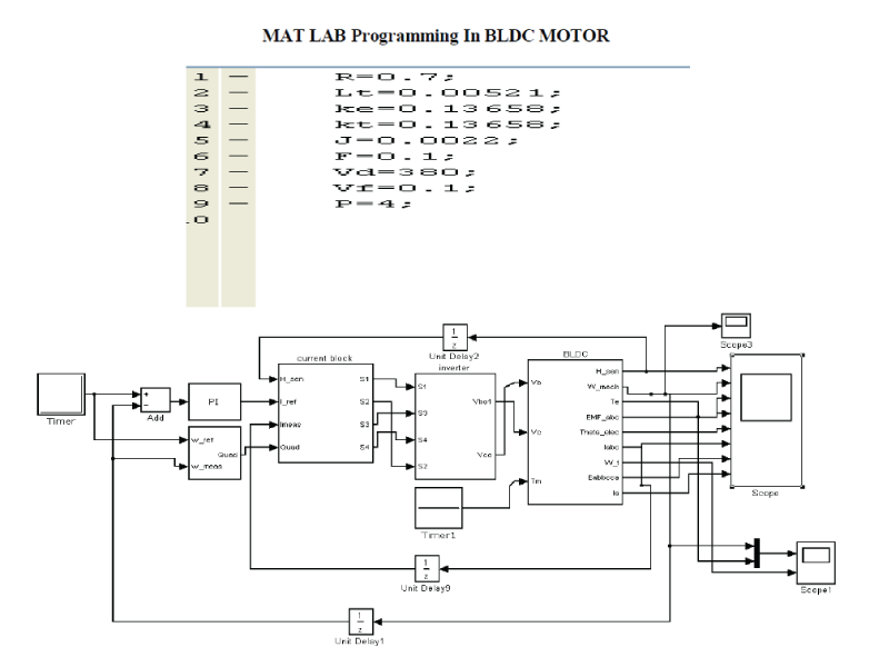
| MAT LAB Programming In BLDC MOTOR |
V.CONCLUSION
|
| The modeling procedure presented in this paper helps in simulation of various operating conditions of BLDC drive system. The performance evaluation results show that, such a modeling is very useful in studying the drive system before taking up the dedicated controller design, accounting the relevant dynamic parameters of the motor. |
| |
Tables at a glance
|
 |
 |
| Table 1 |
Table 2 |
|
Figures at a glance
|
 |
 |
 |
 |
 |
| Figure 1 |
Figure 2 |
Figure 3 |
Figure 4 |
Figure 5 |
 |
 |
 |
 |
| Figure 6 |
Figure 7 |
Figure 8 |
Figure 9 |
|
| |
References
|
- Yong-Kai Lin and Yen-Shin Lai, “Pulse-width modulation technique for BLDCM drives to reduce commutation torque ripple withoutCalculation n of commutation time,” IEEE Transactions on Industry Applications, vol. 47, pp. 1786-1793, 2011.
- H. Wu, et al., “A wide-angle wave control method of reducing torque ripple for brushless DC motor,” Journal of Shanghai University, M vol.11,pp. 300-303, 2007.
- S.S. Bharatkar, et al., “Dual-mode switching technique for reduction of commutation torque ripple of brushless dc motor,” Journal ofIETElectric Power Applications, vol. 5, 193-202, 2011.
- S. S. Bharatkar, R. Yanamshetti, D. Chatterjee, and A. K. Ganguli,“Reduction of commutation torque ripple in a brushless dc motor drive,” inProc. IEEE PECon, 2008.
- H.S. Chuang, Yu-Lung Ke, and Y.C. Chuang, “Analysis of commutation torque ripple using different PWM modes in BLDCmotors,” in Proc.IEEE ICPS, 2009.
|