As sensors are energy constrained devices, the main challenge is to minimize the end to end delay by maximizing the coverage area of sensor nodes. Instead of considering the whole network for packet transmission, nodes are formed as clusters based on region. To achieve energy balanced clustering in the network we use the concept called Minimum Weight Sub modular Set Cover (MWSSC), Distributed Truncated Greedy Algorithm (DTGA) can provide a better solution for Minimum Weight Sub modular Set Cover (MWSSC). Though it can achieve Minimum Weight Sub modular Set Cover (MWSSC), but it consumes more energy for data transmission and for sharing local information among their neighbour nodes in the same cluster. This problem can be solved by infusing Data Fusion in Distributed truncated greedy algorithm.
Keywords |
| Wireless sensor networks (WSN), Minimum Weight Sub modular Set Cover (MWSSC), and Distributed
Truncated Greedy Algorithm (DTGA) |
INTRODUCTION |
| Wireless sensor networks (WSNs) involve deployment of huge number of wireless sensor nodes essentially for
monitoring a certain area and collecting data [1]. These collected data are sent to base station which acts like a control
room. Recent advancement in wireless sensor networks has resulted in a unique capability to the remote sensing
environment. These systems are often implemented in remote or the areas where it is hard to be reached. Hence, it is
difficult in such networks that operate unattended for long durations. Therefore, extending network lifetime through the
efficient use of energy has been a key issue in the development of wireless sensor networks [3]. |
| Wireless sensor network typically consist of tens to thousands of nodes. These nodes collect process and Cooperatively
pass this collected information to a central location [2]. WSNs have unique characteristics such as low duty
cycle, power constraints and limited battery life, redundant data acquisition, heterogeneity of sensor nodes, mobility of
nodes, and dynamic network topology, the energy required to sense events are usually a constant one that can‟t be
controlled. Hence, the energy consumed to keep the communication system on (for listening to the medium and for
control packets) is the dominant component of energy consumption, which can be controlled to extend the network
lifetime. Usually sensor applications involve many sensors deployed together. These sensors form a network and
collaborate with each other to gather data and send it to the base station [4]. The base station acts as the control centre
where the data from the sensors are gathered for further analysis and processing. Network lifetime is defined as the
total amount of time the network was active and could successfully monitor the interested terrain, gather data and relay
them back to the base station or the users concerned. Now the biggest challenge hindering a high Network lifetime is
mainly the limited battery power with which every wireless sensor node is equipped. |
| The process of grouping the sensor nodes in a densely deployed large-scale sensor network is known as clustering.
The intelligent way to combine and compress the data belonging to a single cluster is known as data aggregation in
cluster based environment. The information from the nodes to the sink should be in time. If any delay occurs in
transferring the packet, then the packet will be useless. So the network should have minimum delay. So optimally
choosing the any cast forwarding policy to minimize the expected end-end delay from all sensor nodes to the sink
Communication among number of nodes in a large network for relaying packets consumes lot of energy and takes
multi-hop to reach sink node. Rather we can form clusters with small numbers of nodes. Initially, clusters will be
formed and we can‟t assure that the single node has participated in single cluster. This can be solved using Data fusion
Distributed truncated greedy algorithm (DTGA). In which there is no need for all the nodes to be in active in the
clusters. Only cluster head needs to be in active and the sensor node will wake up when an event occurs. This clearly
shows that the network lifetime can be increased through this data fusion [7]. |
II. SYSTEM MODEL |
| In this work certain assumptions have been made. Firstly we consider that the sensors are statically deployed. This
means that once the sensors are deployed in a certain fashion, these sensors cannot change their coordinates that is they
are not mobile and their positions are fixed. We consider that there are two different states for a sensor. One is the
active state in which it is working for the network and the other is the sleep or the idle state where the sensor is not active but in a kind of hibernating mode. Thus a sensor is required to transmit the packets to their neighboring sensor
nodes and also receive the packets transmitted from those nodes stationed earlier to it. |
III. DISTRIBUTED TRUNCATED GREEDY ALGORITHM |
| Data fusion is generally defined as the use of techniques that combine data from multiple sources and gather this
information in order to achieve inferences, which will be more efficient and potentially more accurate than if they were
achieved by means of a single source. Data fusion occurs at each node using its own data and data from the neighbors.
The data fusion can be implemented in both centralized and distributed systems. In a centralized system, all raw sensor
data would be sent to one node, and the data fusion would all occur at the same location. In a distributed system, the
different fusion modules would be implemented on distributed components. Distributed truncated greedy algorithm
(DTGA) is executed to select a sub modular set cover from all functional sensor nodes. The selected nodes are
activated in the current slot, while other nodes can be turned off. Initially, each sensor sets ACTIVE & SLEEP sets are
null. At iteration k, each sensor i calculates its own energy level. It decides to go to sleep if its energy is less than
threshold energy and transmits a SLEEP message to nodes in region; otherwise it transmits a message ACTIVE to
nodes in region. Upon receiving the decision message from nodes in region, sensor node i first adds node j into SLEEP
state if it receives a SLEEP message from j, and then compares its energy with node j‟s energy. If its energy is
maximum and it has a minimum ID, then it sends an ACTIVE message to the nodes in Region; otherwise, it keeps
silent. This process continues until each node has decided to be either ACTIVE or SLEEP. Since each node has the
information about its neighbour nodes, it will pick the node which is in active state at that time slot to relay the packets.
Clearly there is no global interaction between nodes this leads to multihop and needs more number of nodes. |
IV. ANYCAST PACKET FOWARDING SCHEME |
| This module reduces the delay by using the anycast scheme. This is to optimize the anycast forwarding scheme for
minimizing the expected packet delivery delays from the sensor nodes to the sink. Under traditional packet forwarding
schemes, every node has one designated next hop relaying node in the neighbourhood, and it has to wait for the next
hop node to wake up when it needs to forward a packet. |
| In contrast, under anycast packet forwarding schemes, each node has multiple next hop relaying nodes in a candidate
set and forwards the packet to the first node that wakes up in this forwarding set. It is easy to see that, compared to the
basic scheme in any cast clearly reduces the expected one-hop delay. However, anycast does not necessarily lead to the
minimum expected end-end delay because a packet can still be relayed through a time consuming routing path. |
| Anycast has the potential to reduce the event reporting delay under asynchronous sleep-wake scheduling. In
traditional sleep-wake scheduling a sending node waits for a designated next hop node (Forwarder) to wake up. But in
anycast sleep-wake scheduling the sending node only waits for the first node among candidate forwarders to wake up
which exploits wireless broadcast. The module mainly concentrates on the minimizing the delay and maximizing the
lifetime of wireless sensor network. |
V. CONTROL VARIABLES IN OPTIMAL ANYCAST SYSTEM |
| There are three important things have to be taken into account for the proper functioning of the anycast technique. |
| The three issues are |
| A. Forwarding Set |
| B. Priorities |
| C. Wake-up rates |
| A. Forwarding Set |
| The forwarding set is the set of candidate nodes chosen to forward a packet to nodes. In principle the forwarding set
should contain nodes that can quickly deliver the packet to the sink. However, since the end-end delay depends on the
forwarding set of all nodes along the possible routing paths, the optimal choices of forwarding sets of these nodes are
correlated. |
| B. Priorities |
| We assign priorities to all nodes to make the priority assignment an independent control variable from forwarding
matrix. When multiple nodes send an acknowledgement after the same ID signal the source node will pick the highest
priority node among them as the next hop node. Although only the nodes in forwarding set need priorities, clearly, the
priority assignment of nodes will also affect the expected delay. |
| C. Wake-up Rate |
| The sleep-wake schedule is determined by the wake-up rate of the poison process with which each node wakes up. If
increases, the expected one-hop delay will decrease and so, will the end-end delay of any routing paths that pass through node However, a larger wake-up rate leads to higher energy consumption and reduced the lifetime of wireless
sensor networks. |
VI. CLUSTERING IN WIRELESS SENSOR NETWORK |
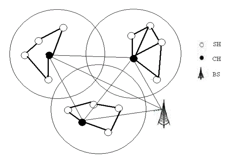
| In clustering, the sensor nodes are partitioned into different clusters. Each cluster is managed by a node referred as
cluster head (CH) and other nodes are referred as cluster nodes. Cluster nodes do not communicate directly with the
sink node. They have to pass the collected data to the cluster head. Cluster head will aggregate the data, received from
cluster nodes and transmits it to the base station. Thus minimizes the energy consumption and number of messages
communicated to base station. Also number of active nodes in communication is reduced. Ultimate result of clustering
the sensor nodes is prolonged network lifetime. In the figure SN indicates the sensor nodes and CH indicates cluster
head and BS indicates base station. |
| A. SENSOR NODE |
| In sensor network, a sensor node is mainly responsible for computation of the extracted data from the local
environment. It processes the extracted data and manipulates the data as per the requirement of an application. All these
activities require real time response, processing and routing of the data It is the core component of wireless sensor
network. It has the capability of sensing, processing, routing, etc. |
| B. CLUSTER HEAD |
| Each cluster usually has a controller node, called the cluster head that has a distinguished role. For instance, the
cluster head may be responsible for controlling the operation of the sensor nodes in the cluster initially; the node will
send its state (ACTIVE/SLEEP) to its neighbour node based on its energy level within its clusters. One among the
active nodes is elected as cluster head. Depending on the number of sleep nodes in the cluster the percentage of
prolongation of the lifetime of the network is calculated. By electing cluster head based on the energy level most of the
node in the cluster will get a chance to be a head. By rotating the cluster-head randomly, energy consumption is
expected to be uniformly distributed. By selecting cluster heads, the energy is saved by minimizing the communication
to only one head node. |
| C. CLUSTER NODES |
| Here forwarding set are called as cluster nodes, these nodes are responsible for relaying the packets as per the
instructions given by the cluster heads. The information related to every cluster nodes will be gathered by cluster heads. |
VII. PROPOSED SYSTEM |
| DATA FUSION -DISTRIBUTED TRUNCATED GREEDY ALGORITHM |
| In order to communicate globally, the coverage range of each node should be improved. For global communication,
we use Data Fusion and any cast forwarding scheme. In Data Fusion, the cluster head for each cluster will be detected
based on its energy level. So, each node in the cluster will get a chance to be a head. By doing so, the life time of
network can be maximized. Cluster head is responsible for gathering information from its cluster nodes (acts as
forwarding set) and communication with its neighbour clusters. If a node wants to send a packet, then that node will
give the information to its cluster head. |
| To achieve energy balanced clustering in the network, we use a concept called Minimum weight sub modular set
cover. It refers to the minimum number of sets that should cover all the nodes to form clusters. The clusters will be
formed based on the region. The information regarding the sensor node radio range and its location is known a priori to
all nodes and this information is made known to all sensor nodes at the time of node deployment. Each node checks its
location with the region point. If it is small when compared to its region point then it decides itself that it belongs to
that particular cluster. If it is greater than it checks with the next neighbour region point and so on to form clusters. |
| After formation of clusters, all sensor nodes in the network calculate their energy level and compare it with the other
nodes in the cluster. If node „i‟ has high energy level then the sensor node is declared as a probable candidate for the
election of cluster head (CH) in the first round. All other sensor nodes, for which the energy level is less opt out from
the process of cluster head selection for the first round and wait for the declaration of first round cluster head, to
associate themselves with one of such declared cluster head. These cluster nodes act as forwarding set for the rest of
time slot. For the first round cluster head election, it has been assumed that the energy of all probable cluster head
candidates is same. Therefore, so it randomly chooses one for the first round. Same process takes place in all the region
simultaneous cluster head selection and cluster formation takes place within the network. |
| The centralized cluster formation process involves transmission and reception of large number of messages between
sensor nodes and sink node. This leads to huge energy consumption for large wireless sensor network, reducing its life
time. It also causes additional delay in cluster formation. The role of cluster head in a cluster must be rotated regularly
amongst the sensor nodes to prolong the life time of sensor network by balancing the energy consumption of various
sensor nodes. Since, cluster head is required to perform extra task of data gathering and communication, compared to
the regular sensor nodes, its energy drains out faster. Therefore, some mechanism must be adopted to rotate the role of
cluster head. The rotation mechanism must ensure balanced energy consumption of all the sensor nodes in cluster. For
our proposed model, the cluster head rotation process has been performed based on the current energy of the nodes in
the clusters. Whenever an event finishes, each node in the clusters again calculates its energy level to elect the cluster
head for the next transmission now this elected cluster head is responsible for both intra and inter communication
between nodes and cluster heads of other clusters in the network. The cluster head will give a signal to other clusters
and on the basis of priorities scheme in any cast packet forwarding, the cluster head will decide, through which cluster,
the packets should be delivered. |
| Consider a node senses an event in any cluster that source node will inform its cluster head about the event. Now the
cluster head gathers information about the destination address and ID of that source node and packet size. This cluster
head will detect for the destination address within its control. If so, it will instruct its source node to relay it to the
destination node directly. Otherwise, it signals the neighbour clusters with the information of packet size, source node
ID, destination address. When a cluster head of neighbour clusters detects a signal then it will analyse for the
destination address to decide whether it‟s in its control or not. If so, it acknowledges the source cluster head with the
information of True. If not, it will acknowledge with the information False and node ID to receive the packet and
calculates the distance between that node and to the destination node. When the source head gets acknowledgements, it
will analyse the acknowledgement to decide which cluster node having less distance to the sink node, this cluster head
will gets the highest priority to relay the packets. The source cluster node will relay the packet to the assigned node in
the next cluster. This process will be done until it reaches the destination.
Algorithm: DF-DTGA |
 |
| Where k indicates iteration, |
| i indicates nodes, |
| Ci indicates Active nodes, |
| Si indicates Sleep nodes, |
| 2. Clusters will be formed based on the region |
| 3. K=K+1 |
| a. Each sensor node i computes its energy level by comparing with threshold energy |
| b. If Ei > Threshold energy and the energy of other nodes then it will be assigned as cluster head
Where Ei represents the energy of ith node |
| c. If a node i wants to send a data, it will send information to its cluster head |
| d. Then the cluster head will check for the destination address, if it‟s in the same cluster, directly
the packets will be sent |
| e. Otherwise, it will give signal to the other clusters with information of destination address, packet
size and Source node ID |
| f. Whichever neighbour cluster head senses the signal check for destination node in its control |
| g. If it is, the reply message contains true |
| h. Else highest energy node in the cluster assigned to receive the packets |
| i. Then this acknowledged head sends signal to other heads to relay packets |
| j. Goto step f |
| 4. Go to step 3 |
VIII. SIMULATION RESULTS |
| In this section we evaluate the performance of Distributed truncated greedy algorithm (DTGA) and Data fusion
distributed truncated greedy algorithm. At first, DTGA (Distributed Truncated Greedy Algorithm) will be executed to
form clusters based on the locations. Each node in the clusters calculates its energy level and check whether it has high
energy to be a cluster head. After the selection of cluster head, it will intimate its status for the current time slot to its
cluster nodes with the information of its ID. Cluster head is responsible for gathering information from its cluster
nodes. Now, the cluster nodes will send a message to its cluster head containing its energy level and ID. Similar
process will takes place in each cluster. |
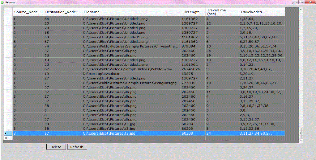
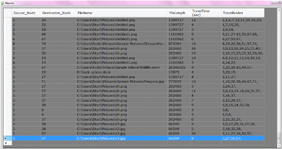
| In the first experiment we consider 1 as source node and 57 as destination node travel time taken to reach the
destination is shown in the simulation result. By infusing the data fusion in distributed greedy algorithm the travel time
taken from source node to destination has been reduced the number of nodes required to relay packet is reduced and
time taken to sink node has been reduced, lifetime of wireless sensor networks has maximized. |
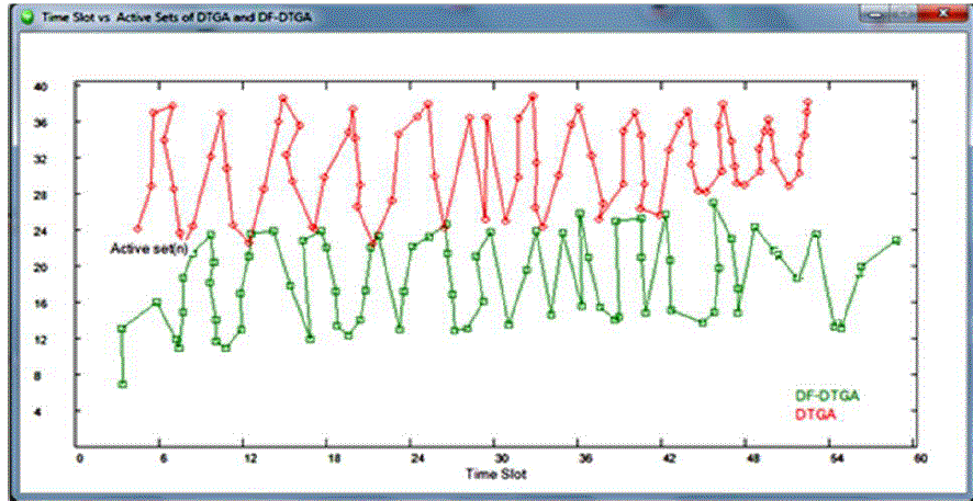
| To demonstrate the advantage of our proposed algorithm, we compare the network lifetime obtained by DF-DTGA
with existing approaches. The results are plotted in fig.4 .We can see that the network lifetime under DF-DTGA is
about 60 time slots the network lifetime slightly increased with the existing approach. The proposed system obtains a
less number of active sensors at each time slot, which is main reason of DF-DTGA, can yield a much longer network
lifetime than existing approaches. |
IX. CONCLUSION |
| We examined the need of clustering in Wireless Sensor Network. We introduced Data Fusion concept in Greedy
Algorithm which is a competitive candidate and provides a better solution for Minimum Weight Sub modular Set
Cover (MWSSC) problem through Distributed Truncated Greedy Algorithm. By using Data Fusion in Distributed
Truncated Greedy Algorithm, the number of nodes required to relay packets has been reduced. Since cluster head only needs to be in active state and the cluster nodes can be in sleep state. This leads to less consumption of energy and so
the lifetime of Wireless Sensor Network has maximized. And the time taken to reach the sink node has been reduced by
increasing the coverage area of each node in the network. |
X. ACKNOWLEDGMENT |
| We take this opportunity to express our deepest gratitude and appreciation to all those who have helped us directly or
indirectly towards the successful completion of this paper |
Figures at a glance |
 |
 |
 |
 |
| Figure 1 |
Figure 2 |
Figure 3 |
Figure 4 |
|
| |
References |
- X. Li,H. Frey,N.Santoro,and I.Stojmenovic, ”Strictly Localized Sensor Self-Deployment for Optimal Focused Coverage,” IEEE Transaction on Mobile Computing, Vol. 10, no. 4, pp. 1520-1533, 2011.
- G.Xing,R.Tan,B.Liu,J.Wang, X Jia and C.Yi, ”Data Fusion Improves the coverage of Wireless Sensor Networks”, Proc.MobiCom, pp. 157-168, 2009.
- L.Wolsey, ”An Analysis of the Greedy Algorithm for the Sub modular Set Covering Problem”, Combinatorcia, Vol.2 no. 4, pp. 385-393, 1982.
- A.Gallais, J,Carle, D.Simplot-Ryl and I.Stojmenovic, „Localized sensor Area coverage with Low communication Overhead‟, IEEE Trans.Mobile Computing, vol.7, no.5, pp.661-672, May 2008.
- W.Wang, V.Srinivasan, K.C.Chua, and B. Wang, “Energy-efficient coverage for target detection in wireless sensor networks”, In IPSN, pp. 313-322, 2007.
- W-P. Chen, J.C.Hou, and L.Sha, “Dynamic clustering for acoustic target tracking in wireless sensor networks”, IEEE Trans. Mobile Comput., Vol 3, No.\3, pp. 258-271, 2004.
- Z.Chair and P. Varshney, “Optimal data fusion in multiple sensor detection systems”, IEEE Trns.Aerosp. Electron. Syst.,Vol. AES22, pp. 98-101, Jan. 1990.
- MihelaCardei T.Thai,Ying,Shu Li Weili Wu, ”Energy Efficient Target coverage in Wireless sensor networks”, IEEE INFOCOM, 2005.
- Nandini.S.Patil and P.R.Patil,”Data Aggregation in wireless sensor network”, IEEE International Conference on Computational Intelligence and Computing Research, 2010.
- Ameer Ahmed Abbasi and Mohamed Younis, “A Survey on Clustering Algorithms for Wireless Sensor Networks”, Elsevier Journal of Computer Communications, Vol. 30, pp. 2826–2841, October 2007.
|