In today’s world everything is fast paced and internet as become necessity of life we need it at every step. With the invention of smart phone GPS enabled cell user can ask for any service via Information service and Application provider from anywhere any time. This business model is known as moving commerce .It provides Location based services through moving phone. One of the active topics in mining is the mining and prediction of moving movements and associated transactions. Most of existing studies focus on discovering moving patterns from the whole logs. The issue with this method is that it does not provide accurate information as it depends on spatial clustering where as Location based services require non spatial clustering. The other issue with it is that most methods requires user to set the parameters which is highly impossible in an active environment. Moreover in moving environment the user profiles are seldom known but what we know is the moving transaction patterns. In the paper we will use an algorithm, namely, Temporal Moving Sequential Pattern Mine based on clustering, to discover the Cluster-based Temporal Moving Sequential Patterns .User clusters are constructed by a algorithm named Cluster- Object-based Smart Cluster Affinity Search Technique similarities between users are evaluated by the proposed measure, Location-Based Service Alignment (LBS-Alignment).In the algorithm is also proposed to use time as also one of the dimensions where similar moving characteristics exist.
Keywords |
| clustering, location based service, gps, aproiri, transactions. |
INTRODUCTION |
| Energy management is a new forming issue throughout the world. Power production facilities have to produce
energy continuously prepared for heavy fluctuations in consumption, especially when alternative sources are used, or in
case of a sudden breakdown. They have to prepare peaks, but in periods when there is less consumption they can lead
remaining energy into storage. There are many kinds of techniques to store energy: batteries, large super-capacitors, or
large mechanical systems. All of these methods are very expensive in such large scale. Running plants below full
capacity is inefficient at the same time; the cost of the same amount of power is more expensive than running on full
capacity. In storing and retrieving energy there is always a certain loss. Responding to immediate fluctuations is
however impossible, therefore energy production utilities always produce more energy that expected to be needed. |
| The Energy Provider (called Utility from now on) places meters to customer’s household to measure the overall
power consumption at all time. These meters are read periodically by the Utility. The energy bill is calculated based on
the read consumption. The main idea behind smart grids is that the utility should be able to balance the load by getting
customers to shift their load to off-peak periods. The simplest method would be to charge energy on different prices at
off- and on-peak periods. Other aspect of smart grids is the ability to feed power to the grid, which is necessary in case
of alternative power production. The former consumer may become a provider by investing into energy production
technologies using alternative forms of energy. In order to feed energy back to the grid smart power meters are needed. |
| To summarize the introduced facts in order to increase efficiency of energy production more intelligence has to be
put in the system beginning with the consumer side. While there is significant emphasis on home intelligence and
network integration the price of achieving it is not to be neglected. The additional energy, cost, and effort of installing
and maintaining such a system determine its competitiveness on the market. We are going to present a novel energy
saving approach developed within the AIM project which serves as a platform for smart home integration leaving the interconnection technology freely chosen. During the design of the system scalability and low-power requirements
were also taken under consideration. Built on that platform we prove that DECT is candidate technology. |
II. BACKGROUND AND RELATED WORK |
| Several standardization bodies are preparing network standards to be fit in the smart home and smart grid concept.
The leading standardization body is CENELEC (European Committee for Electro-technical Standardization) with the
EN 50090 standards about Home and Building Electronic Systems (HBES). The European Commission has also
launched several projects dealing with efficient energy-management. |
| The SmartHouse/SmartGrid FP7 European project (http://www.smarthousesmartgrid.eu) specifically focuses on
connecting smart houses and smart grids and solving load balancing by dynamic electricity pricing. For connection
between the utility and the smart meter it targets to define high level (web services based) interfaces. In [2] they present
their developed service-based system based on smart houses and smart grids. Other decentralized approaches include
decentralized decision based on information from a central control station [8] and agent based control for the electricity
infrastructure is presented in [7]. It provides market-based control concept for supply and demand matching (SDM) in
electricity networks. In [6] a business model is presented for dynamic service oriented energy network and its security
and business aspects are discussed. |
| Contrary to other solutions our system targets not just smart metering and control, but also energy profiling of
appliances and the intercommunication with the energy provider for the benefit of both the customers reducing energy
consumption and advanced pricing, and for the provider making possible better energy management and use of
renewable power resources. |
| The general architecture of the smart home used in our research is presented in Section 3. In Section 4 we describe
our smart home system realization. The communication protocol we have developed is introduced in Section5. The
provided services of our system are described in Section 6. Finally in Section 7 we conclude our paper. |
III. THE SMART HOME SYSTEM |
| The AIM project’s [12] primary focus is to foster a massively used technology for profiling and optimizing the
energy consumption patterns of home appliances. The purpose of the project is to create an end-to-end system where
virtualised household appliance functions and utility services are deployed under a common logic on the future’s home
gateway. AIM targets creating an embedded Energy Management Device (EMD) which can provide basic energy
management functions for existing home appliances. Based on the EMD the target is to achieve energy-saving by
recognizing pre-defined energy-patterns of home appliances. The project also aims to create a SOA (Service Oriented
Architecture) based logic on the home gateway which can integrate the EMD managed home appliances into the home
network. Contrary to existing power meters, an EMD is designed to be cheap with most data processed on the gateway. |
| Although complete logic layer structure is being defined for interworking of components of the system, the physical
layer communication interfaces are not strictly bound allowing the manufacturers to use their preferred technology. |
| We are going to present a concept developed in the AIM project which will serve as the basis of our research. The
energy management model we are going to present aims for the individual appliances in the household to achieve a
smart home system. The system targets the following goals: |
| - Provide a device which can integrate the home appliances into the home network |
| - Define energy profiles for home appliances with which energy states can be assigned to the appliances without
constant metering |
| - Provide guidance for manufacturers how to submit state information for energy profiling |
| - Record energy profiles for ordinary appliances |
| - Switch off appliances which indicate their stand-by mode |
| - By accessing utility services, real-time price calculation according to selected appliance profile |
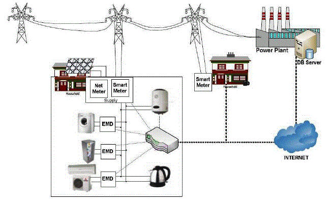
| The model with the key components is presented on Fig. 1. The EMD serves as a communication interface between
the energy management functions of the attached appliance and the home network. |
| With the energy patterns of AIM compliant devices the consumption of an appliance can easily be determined by
requesting the state of the appliance thereby excluding the need for constant monitoring. Additionally by physically
switching off devices which indicate being in stand-by mode further energy can be saved. The energy provider (Utility)
plays a great role in the AIM system. By requesting energy prices from the service of the utility, and based on the
appliance profiles, the system ca pre-calculate the price of operating an appliance with a certain program or for a set
time. Cost saving can be achieved with the system by shifting the appliance operation for a time when energy prices are
lower (e.g. at off-peak periods). The smart logic residing on the home gateway runs the service which manages the
appliances and provides a control point for remote management. |
IV. COMPOSITION OF OUR SMART HOME SYSTEM |
| Based on the concepts described above in this chapter we present our developed solution. We aimed on developing a
system by which home appliances can be connected to a networked, remotely accessible system. The middleware
(hardware and software components) which makes it possible is called the Energy Management Device, i.e. it is the
building block for smart appliance integration. |
| The system is able to virtualize each appliance on the Home Gateway for the home and external network for
management purposes. We have implemented the following functions inside the EMD: consumption monitoring, basic
power control, device profile programming, device profile identification. |
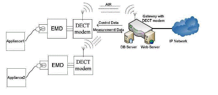
| The general architecture on the modular level of the achieved system is presented on Fig. 2. The Home Gateway
communicates the Energy Management Devices through a standard interface (in our implementation via DECT). The
appliance gets its power through the EMD which can measure its consumption. According the programmed device
profile the EMD can assign power state to the appliance without the need to constantly monitor its consumption. |
| A. The Energy Management Device |
| The main idea behind the energy management device is to place the household appliances under common
management logic in the home. These devices are designed to be cheap and simple, but not to replace the smart meters
which are very expensive and very robust equipment. The actual consumption is monitored by the utility installed smart
meter, and the production with the net meter and used for billing by the utility. The EMDs are to be used by appliances
to monitor consumption and provide remote control through the management logic hosted on the home gateway. |
| There are two basic functions that the EMD should be capable to fulfil: Power consumption metering and power
control. It should possess one communication interface towards the home gateway to be able to access its functions.
The device has to be cheap in order to be competitive on the market and has to operate with low-power. Additionally
the EMD connected to an appliance could measure energy efficiency, to signal any unusual behaviour of the appliance,
and even to apply safety precautions immediately to prevent damage, or injuries. |
| The EMD we have realized comprises a power metering logic and a power control logic. The power line goes
through the power metering logic and the power control logic in that order as presented on the above figure. Therefore
the measurements will not be altered by the power control logic. The power metering and power control logics are
controlled by a microcontroller which needs negligible power for operation. Low-power requirements are met by the
using the low-power sleep mode of the microcontroller. The DECT interface wakes up only before the assigned
timeslots to receive and send, otherwise goes to low-power state. |
| The power metering logic has to measure the real power of the load real-time and performs constant integration to
calculate and store consumption. Through the power control logic it has to be capable to switch off the load. For power
measurement two circuits are needed, one for voltage measurement and one for current measurement. For current
measurement Hall sensors can be used which measure magnetic field of the conductor that is proportional of the
current. With this solution no physical contact has to be made with the load to measure current. |
| For the power control logic the easiest solution is to use a relay which can be driven with a low-voltage output of the
microcontroller. Contrary to the large form factor of the relay a TRIAC can also be used, but this requires zero crossing
detection. The latter has an additional advantage that is adjustable power control e.g. for light dimming. |
| B. Communication between EMD and Gateway |
| We have considered many wired and wireless technologies for the communication interface. Our first candidate was
a power line based interface, however a KNX based EMD realization has already been achieved in the project [1]. |
| Our choice, the DECT technology has many advantages making it a competitor against other wireless technologies,
even against power line. Compared to IEEE 802.11 WLAN [10] it is less resource demanding and considerably
cheaper. Contrary to ZigBee [11] it operates in a protected frequency range. Z-Wave [14] could be a good alternative,
however it is proprietary technology. The most significant benefit is nevertheless the existing infrastructure which is
already available in numerous households, and by the recommendation of the Home Gateway Initiative it will be
included in every home gateway in the future [5]. DECT is a widespread technology, DECT phones are widely used for
wireless extension of the PSTN service because they are cheap and reliable. |
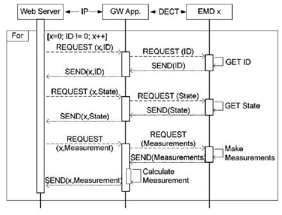
| By request on the gateway (either from the web server or the UPnP server) towards the EMDs a data call is used,
which provides a packet switched connection. We have defined a simple request-response based protocol over this
connection (Fig. 4), which is presented in section 5. |
| The integration of different technologies in the Home is also pursued by the Home Gateway Initiative (HGI) defines
requirements, and use cases for the Home Gateway, which is to be the central service provider in the home. In
connection to the home gateway concept Lantiq (a leading company in access and home networking) will be releasing
the first CAT-iq compliant Home Gateway and handset products. |
| Our goal was to find a gateway platform which supports DECT base station functionality and supports new
generation DECT functions. We have selected Lantiq’s ARX based reference solution with voice support. The
operating system running on this chip is the popular OpenWRT (http://www.openwrt.org/), which is a modular
operating system allowing easy development and cross compilation to many types of devices. For the basis of the
operating system Linux kernel is used. |
| Low-power consumption is a very important issue on the gateway as well. The Linux ACPI power management can
be used for resource management. The power management features of the ARX platform can be reached using a
specific ACPI driver. The Linux resource management provides an API to control the power states of the gateway [13]. |
V. USING DECT/CAT-IQ FOR EMD-GATEWAY COMMUNICATION |
| Digital Enhanced Cordless Telecommunications was originally a wireless telephony standard. During the call, the
portable part (PP, handset) and the fixed part send (FP, base station) uplink and downlink data accordingly in their
allotted timeslot. The original DECT standard has defined the possibility to create DECT cellular networks.
Distribution of base stations in an area increases the coverage of DECT, and also the number of usable devices. |
| Currently DECT is undergoing a major transformation. The upcoming CAT-iq (http://www.cat-iq.org) set of
standards which are to replace DECT have many interesting features [3]. The main goal is to grow out from the former
‘wireless telephony only’ scenario and to become a general wireless technology supporting QoS and using above IP
communication. CAT-iq has a generic goal to offer internet connectivity to home appliances, which require low datarate,
but quality of service. Other application profiles, like sensor network integration, and home control are under
definition. |
| We have implemented our solution above the standard DECT operation using the data call feature defined in the
Dect Packet Radio Service (DPRS) standard [9]. Accordingly the call is initiated by the portable part (which is attached
to the EMD) by request of the gateway. The length of a standard DECT frame is 40 bytes, so the maximum length of
the Data field (data length) is 35 bytes therefore no message has to be fragmented. |
| The simple messages needed for the basic functionality is shown in the tables below. The gateway can send turn on
or off messages and waits for a response. There is a request state message to get the state of the EMD. The EMD sends
messages only if requested to do so by a request state, a request measurement or a request ID message. |
| Since the system has to support multiple appliances it is necessary to distinguish these from one another. For this
purpose each EMD has an identification number (ID number) which is either a serial number (unique, unchangeable,
and set by the manufacturer), or a number entered by the user. |
| In addition to the EMD messages the gateway can request the number of connected EMDs. Throughout the DECT
connection on the gateway the connected EMD’s are distinguished by the frequency and timeslot on which the
communication is taking place. When the list of EMDs is requested from the gateway the gateway collects the
frequency-timeslot pairs where it communicated with an EMD. |
| According to the standard, a DECT system can support 24 devices on each of the 10 frequencies, altogether 240 and
120 in full duplex mode. Therefore in theory 120 hand phones, called Portable Parts (PP) can be used in a system with
a base station called Fixed Part (FP) operating on different frequencies. The communication is robust, retransmission is
handled by the DECT protocol, latency is very low, around 10ms |
VI. SERVICE ACCESS AND MANAGEMENT |
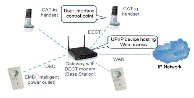
| The smart home system provides interfaces for remote access on IP in a form of a website hosted on the gateway
itself and an UPnP service for general remote interaction. On the gateway we developed an application which
implements an UPnP Controller for each EMD discovered in the system. The control point to our management system
is a webpage hosted on the gateway itself. |
| There is a web server established on the gateway which hosts the website for our energy management system. There
is a login page performing authentication, after successful login the management page is displayed. This page consists
of the listing of discovered appliances, showing the status of the appliances (on/off) and showing momentary
consumption of the appliances. There are controls to change the status of the appliances. After login each of the
appliances having an EMD is listed with their state, and momentary consumption. We have also implemented UPnP
server functionality on the gateway to remain consistent with the management interfaces used in the project. The highlevel
smart home logic implemented in the project separately accesses all the devices via UPnP. |
| Our implementation is based on libupnp which is an open-source UPnP development kit. This application is the one
which performs the DECT-UPnP bridging by accessing the driver of the DECT module. Our EMDs are hosted as UPnP
devices with the following services: appliance name request, status request, momentary energy request, and integrated
consumption request for a time interval. The overview of components and offered interfaces are presented in Fig. 5.
With the DECT infrastructure we plan to implement a user interface on the handsets, which can host a subset of the
system’s functions. |
VII. CONCLUSIONS |
| An interactive energy management system is very beneficial for the consumer, the provider, and indirectly for the
environment, therefore it is demanded in the future. |
| We have introduced a model for a future smart gird, where smart homes are the key actors. The smart home is built
up from smart appliances which provide energy management functions. To integrate existing appliances to the smart
home we have created an energy management device (EMD). The EMDs are connected to the home gateway through a
DECT wireless interface which is already present on existing gateway platforms. This solution does not require
additional expensive hardware. The website on the gateway provides remote user access, while the UPnP server eases
the smart home integration to a smart grid. From the basic functions a complex logic can be developed in the future in
the Home Gateway achieving automated control of appliances using the interface provided by the Utility for its
management functions. |
| We have designed a simple, robust communication protocol between the EMD and gateway, based on the
possibilities provided by the DECT system especially considering the upcoming CAT-iq standard. |
| Our goal with this system was to provide a cheap solution for the household to turn their home smart. Intelligent
energy management is needed in the future smart grids. |
ACKNOWLEDGMENT |
| The presented architecture has been elaborated in the frame of the project “A Novel Architecture for Modeling and
Virtualising Energy Consumption of Household Appliances-AIM” [12]. The research leading to these results has also
received funding from the Inter-University Cooperative Research Centre, Dept. of Telecommunications and Media
Informatics, Budapest University of Technology and Economics, Budapest, Hungary. |
Tables at a glance |
 |
| Table 1 |
|
| |
Figures at a glance |
 |
 |
 |
 |
 |
| Figure 1 |
Figure 2 |
Figure 3 |
Figure 4 |
Figure 5 |
|
| |
References |
- Tompros, S., Mouratidis, N., Hrasnica, H., Caragiozidis, M.: A novel power line network architecture for managing the energy resources of the residential environment. In: 13th IEEE International Symposium on Power Line Communications and its Applications, Dresden (March 2009)
- Kok et al.: Smart Houses For A Smart Grid. In: 20th International Conference on Electricity Distribution CIRED, Prague (June 2009)
- ETSI TS 102 527, Digital Cordless Enhanced Telecommunications; New Generation DECT
- CAT-iq at a Glance, Global Technology for Broadband Home Connectivity, DECT Forum (2009)
- Home Gateway Technical Requirements: Residential Profile, Version 1.0, Home Gateway Initiative (29.04.2008)
- Karnouskos, S., et al.: An Advanced Metering Infrastructure for Future Energy Networks, New Technologies, Mobility and Security, pp. 597?606. Springer, Heidelberg (2007)
- Kok, J.K., Warmer, C.J., Kamphuis, I.G.: PowerMatcher: multiagent control in the electricity infrastructure. In: Proceedings of the Fourth International Joint Conference on Autonomous Agents and Multiagent Systems, AAMAS 2005, pp. 75?82. ACM, New York (2005)
- Nestle, D., Ringelstein, J.: Bidirectional Energy Management Interfaces in distribution grid operation. In: 3rd Int. Conf. on Integration of Renewable and Distributed Resources (2008)
- Draft ETSI EN 301 649 V1.4.2, DECT Packet Radio Service (DPRS) (May 2007)
- L.M.S.C. of the IEEE Computer Society. Wireless LAN medium access control (MAC) and physical layer (PHY) specifications. IEEE Standard 802.11, 1999 edn. (1999)
- Wireless medium access control and physical layer specifications for low-rate wireless personal area networks. IEEE Standard, 802.15.4-2003 (May 2003) ISBN 0-7381-3677-5
- The, AIM Consortium, AIM ? A Novel Architecture for Modeling, Virtualising, and Managing the Energy Consumption of Household Appliances, http://www.ict-aim.eu
- Scalopes deliverable DT3.2.1 - WPT3 Resource Management, http://www.scalopes.eu/
- Z-Wave Alliance, http://www.z-wave.com
|