Keywords
|
| SSSC FACTS, UPFC, Voltage Source Convertor, Power Flow Controller |
INTRODUCTION
|
| This paper describes an active approach to series and shunt line compensation. The compensators used for analysis are SSSC and UPFC can provide controllable compensating voltage over an identical capacitive and inductive range, independently of the magnitude of line current. In addition to reactive compensation it can also compensate the voltage drop across the resistive component of the line impedance. The compensation of the real part of impedance can maintain high X/R ratio even if the line has very high degree of series compensation. |
| The efficient three phase ac power transmission is a main concern of power system engineer. The three phase ac transmission from generating point to consumer end have certain limitation as voltage regulation and other losses due to presence of inductance and capacitance of the transmission line. As per researches of these days’ shows High Voltage Alternating Current transmissions becomes more efficient and economical by using FACT devices. In a power network if the VARs generated are equal to the VARs consumed by passive elements used in transmission line are equal then it is said that the sending voltage and receiving voltage are equal. But if otherwise the VARs generated is not equal to the VARs consumed then sending end voltage will not be equal to the receiving end voltage. This variation in voltage i.e. voltage sag or increment in voltage, are undesirable condition. Hence to stop this variation in voltage various compensation techniques are used. On the basis of VAR requirement series and shunt compensation techniques are used. The compensation techniques are capable to control sending end and receiving end voltages through voltage regulation at the respectivebuses, the phase angle between the sending end voltage and receiving voltage, the series reactance. |
| The better utilization of power system are made possible by fast growing of power electronics devices. at the load end have more advantage than classical 3 phase power transmission. Methods because of non-effectiveness of inductance and capacitance for HVDC power transmission system[2]. |
| The power flow between two interconnected systems is given by the equation. |
 |
| Hence from above equation it can be said that power flow of any tie line can be controlled by varying any of one of above given four parameters. |
| FACTS controllers are based on voltage source converters and includes devices such as Static VAR Compensators (SVC), static Synchronous Compensators (STATCOM), Thyristor Controlled Series Compensators (TCSC), Static Synchronous Series Compensators (SSSC) and Unified Power Flow Controllers (UPFC)[2].Among them UPFC is the most versatile and efficient device which was introduced in 1991. In UPFC, the transmitted power can be controlled by changing three parameters namely transmission magnitude voltage, impedance and phase angle. |
UNIFIED POWER FLOW CONTROLLER (UPFC)
|
| [A] INTRODUCTION |
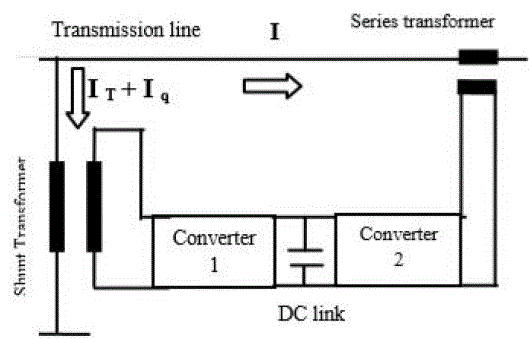
| The UPFC is considered as poly-functional controller device which can be used in various compensation technique ,in this compensation technique , voltage source converter(VSC)having back to back arrangement are used. In back to back arrangement of VSC a series and shunt converter are used. Since these converters are employed with transmission line in series and shunt manner. |
| Each converter in this arrangement has capability to control active power flow in either direction independently. The function of shunt converter is to supply or absorbed the real power required by series converter; both the converters are connected through DC link. The DC link makes the real power exchange efficient and convenient in between both the converters. The shunt converter can also be supply or absorb reactive power hence the voltage level can also be control easily. |
| [B] MODELING OF UPFC |
| The control system described in the previous chapter was derived by assuming that the series and shunt converter are treated as ideal controllable voltage sources that the value of fundamental component of the line currents are easily available . The UPFC is modelled by combining the series and shunt branches coupled by the DC voltage control branch. Local load is added at port 1 of the UPFC. The organization of UPFC modeling blocks are shown in below fig.1. |
| The UPFC has many possible operating modes. (1)VAR control mode:-The reference input is a simple VAR request that is maintained by the control system regardless of bus voltage variation. (2) Automatic voltage control mode:-The shunt inverter reactive current is automatically regulated to maintain the transmission line voltage at the point of connection to a reference value with a defined slope characteristics the slope factor defines the per unit voltage error per unit of inverter reactive current within the current range of the inverter. In Particular, the shunt inverter is operating in such a way to inject a controllable current into the transmission line. The figure 2 shows how the (UPFC) is connected to the transmission line. |
STATIC SYNCHRONOUS SERIES COMPENSATOR (SSSC)
|
| [A] INTRODUCTION |
| The Static Synchronous Series Compensator (SSSC) is a device that belongs to the Flexible AC Transmission Systems (FACTS) family using power electronics to control power flow and improve power oscillation damping on power grids. The SSSC injects a voltage in series with the transmission line where it is connected. The SSSC contains a solidstate voltage source inverter connected in series with the transmission line through an insertion transformer. This connectionenables the SSSC to control power flow in the line for a wide range of system conditions.SSSC is connected in series with transmission line which control the source voltage, phase angle and inject it in same sinusoidal form. |
| The reactance of the electric power system have an important role for power flow, it influence the power flow direction .Active and reactive power flow increase or decrease depends on the reactance is inductive or capacitive. The reactive compensation going in positive direction represents that the reactance is capacitive and decreasing while the active and reactive power is increasing .Its shows that the electric power flow influenced by variable reactance, of the transmission line .Static synchronous series compensator (SSSC) uses a voltage source converter to inject a controllable voltage in quadrature with the line current of a power network. Such a device is able to rapidly provide both capacitive and inductive impedance compensation independent of the power line current. Moreover, an SSSC with a suitably designed external damping controller can also be used to improve the damping of the low-frequency power oscillations in a power network. |
| The SSSC injects the compensating voltage in series with the line irrespective of the line current. The transmitted power Pq, therefore becomes a parametric function of the injected voltage, and can be expressed as follows: |
 |
| The SSSC, therefore can increase the transmittable power, and also decrease it, simply by reversing the polarity of the injected ac voltage. The reversed (180° phase-shifted) voltage adds directly to the reactive voltage drop of the line as if the reactive line impedance was increased. Furthermore, if the injected voltage is made larger than the voltage impressed across the uncompensated line by the sending- and receiving end systems, that is if |Vq| > |V1 - V2|, then the power flow can reverse. Apart from the stable operation of the system with both positive and negative power flows, it can also be observed that the SSSC has an excellent (sub-cycle) response time and that the transition from positive to negative power flow through zero voltage injection is perfectly smooth and continuous. |
| [B]MODELING OF SSSC |
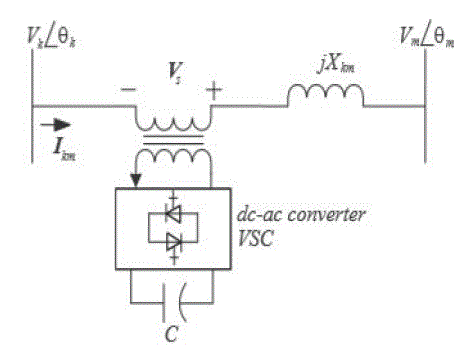
| The SSSC is based on a VSC device that injects a voltage in series with the transmission line. The transient stability model used in this paper is extracted from [2], where the SSSC is represented by a series-connected voltage phasor source VS, as depicted in Fig.4, which is always kept in quadrature with the line current phasor, so that the SSSC can exchange only reactive power with the system. Thus, the controllable parameter in this case is the magnitude VS, which is used to regulate active power flow. This model yields the following algebraic power flow equations between the k and m nodes in Fig.4: |
 (2) (2) |
| Pmk = − Pkm |
| Qkm = (1 + Ψ)VkBkm [Vk − Vmcos(θk − θm)] |
| Qmk = (1 + Ψ)VmBkm [Vm − Vkcos(θk − θm)] |
| where Ψ = Vs/pV 2 k + V 2 m − 2VkVm cos(θk − θm),and Vk∠θk, Vm∠θm, and Bkm = 1/Xkm are defined in Fig4. |
| The basic control strategy in Fig.3 is adopted here to regulate the active power flow. Since the main aim of this SSSC model is to control the active power through the transmission line where is embedded, a POD input signal is used in its control to damp power oscillations. This signal comes from the POD control depicted in Fig.4, which basically has the same control structure as a typical PSS [1]. The real part of this impedance represents the ohmic losses of the power electronic devices and the coupling transformer. The imaginary part of this impedance represents the leakage reactance of the coupling transformer. |
RESULT AND DISCUSSION
|
| [A] SIMULATION RESULTS OF SSSC |
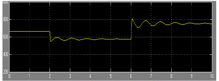
| The fig. 5 shows the phase voltage at receiving end bus bar after installing SSSC in transmission line.The use of SSSC improves the voltage profile in comparison to response of transmission line without having SSSC. |
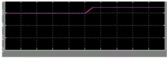
| Fig.6 shows the active power drawn by load, from waveform it is clear that oscillation stops after few cycle. |
| [B] SIMULATION RESULTS OF UPFC |
| phase power available at sending end station having following current waveform next fig. shows active as well as reactive power flow at sending end station buss bar.The waveform shown below represents phase voltage at receiving end and active power drawn by load. |
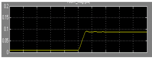
| The power transfer capability of long transmission lines is usually limited by their thermal capability. Utilizing the existing transmission line at its maximum thermal capability is possible with UPFC.The waveform shown below represents active flow. |
CONCLUSION
|
| In power system transmission, it is desirable to maintain the voltage magnitude, phase angle and line impedance. Therefore, to control the power from one end to another end, this concept of power flow control and voltage injection is applied. Modeling the system and studying the results have given an indication that UPFC are very useful when it comes to organize and maintain power system. Following conclusions are made- |
| 1. Power flow control is achieved and congestion is less. |
| 2. Transient stability is improved. |
| 3. Faster Steady State achievement. |
| 4. Improved Voltage Profile |
Figures at a glance
|
 |
 |
 |
 |
| Figure 1 |
Figure 2 |
Figure 3 |
Figure 4 |
|
 |
 |
 |
| Figure 5 |
Figure 6 |
Figure 7 |
|
References
|
- P. Kundur, Power System Stability and Control. McGraw Hill, New York 1994.
- R. Mihalic and U. Gabrijel,“A structure-preserving energy function for a static series synchronous compensator,” IEEE Transactions on Power Systems, vol. 19, no. 3, pp.1501–1507, 2004.
- Povh, D. 2000. “Modeling of FACTS in Power System Studies”. Proc. IEEE Power Eng. Soc. Winter Meeting. 2:1435–1439.
- Acha, E., C.R. Fuerte-Esquivel, H. Ambriz-Pe´rez, and C. Angeles-Camacho. 2004. FACTS: Modelling and Simulation in Power Networks. John Wiley and Sons: West Sussex, UK.
- Radman, G. and R.S. Raje. 2007. “Power Flow Model/Calculation for Power Systems with Multiple FACTS Controllers”. Electric Power Systems Research. 77:1521–1531.
- Stagg, G.W. and A.H. Ei-Abiad. 1968. Computer Methods in Power Systems Analysis. McGraw-Hill: New York, NY.
- Hingorani, N.G. and L. Gyugyi. 2000. Understanding FACTS: Concepts and Technology of Flexible AC Transmission Systems. Wiley–IEEE Press: New York, NY. ISBN: 0-7803-3464-7.
- Zhang, X.P., C. Rehtanz, and B. Pal. 2006. Flexible AC Transmission Systems: Modelling and Control. Springer Verlag: Berlin, Germany.
- Zhang, X.P. 2003. “Advanced Modeling of Multicont rol Functional Static Synchronous Series Compensator (SSSC) in Newton–Raphson Power Flow”. IEEE Trans. Power Syst. 18(4):1410–1416.
|