Keywords
|
| BLDC motor, PWM inverter, Multiphase, Speed Control, Cohen Coon Tuning |
INTRODUCTION
|
| BLDC motor have some advantages comparing with brush dc motors and induction motors. The use of strong permanent magnets energy wastage of motor is less so the efficiency will be high.These motors are less weight, volume ,high reliability,less noise and less maintenance. Due to these advantages the use of motors is growing rapidly in various applications [1] |
| BLDC motor with more number of phases has more advantages than three phase. It can reduces stator current in each phase without increasing the voltage, reduces torque ripples, reduces amplitude and increasing frequency of torque pulsation. For aerospace, military applications, fault tolerant is important consideration. Multiphase motors are more fault tolerant comparing with conventional three phase. The motor can be operated normally if one or more phases are failed. [6]-[12].However despite of this advantage the criticism against higher number of phases is that its complex control scheme and higher cost. This problem can easily solved with the development of DSP controller. Thus multiphase motor drive. can be good choice where high reliability and power density required. In areas such as aerospace,,ship propulsion, military applications where requirements are not opperesive when compared with overall demands.[2].In the past review of multiphase BLDC five phase motor drive seven phase motor drive and nine phase motor are presented. In reviewing the articles a eleven phase motor drive is not yet been analysed in the previous studies. In this paper eleven phase BLDC motor drive and components of mathematical model are presented in MATLAB/Simulink software. |
ELEVEN PHASE BLDC
|
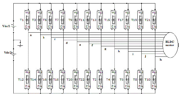
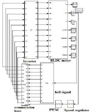
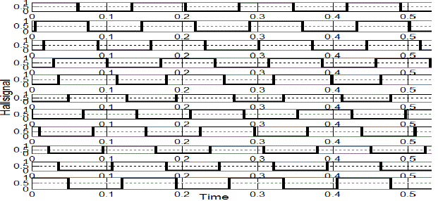
| The overall system configuration of eleven phase BLDC motor drive is shown in Fig 1. The PWM inverter topology composed of 22 switch voltage configuration with constant dc link voltage. The PWM inverter and position sensors are used for current commutation which replaces the function of brushes and commutator. The hall sensors are used for sensing the position and triggering the switches in the PWM inverter according to sensor signals which is electronic commutation. |
| The flux distribution in BLDC motor air gap is not sinusoidal, rotating field control and axial conversion used for induction and synchronous motor cannot be used for modelling BLDC motor. The harmonic modelling of BLDC require large amount of computations. Most of these methods not give clear image for current variables on inverter voltage. The method based on finite element analysis require complex mathematical equations and not capable of expressing switching behaviour of the drive system. |
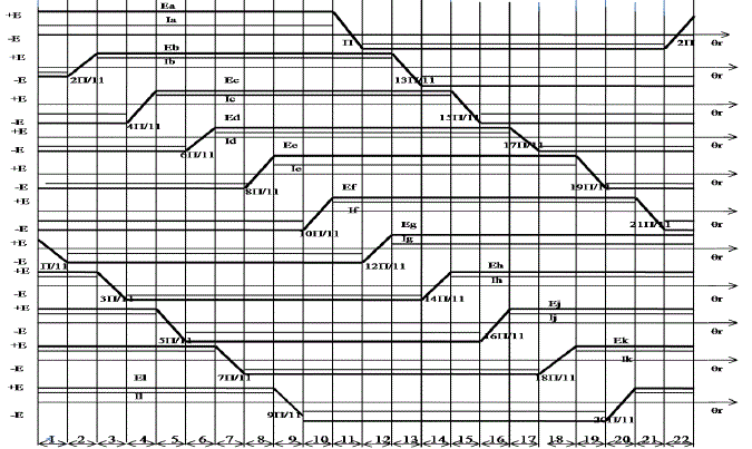
| 22 switch 11 phase PWM inverter is formed by generalising 5 phase, 7 phase, 9 phase models. Inverter performance includes 22 modes according to current conduction states as in fig 2 |
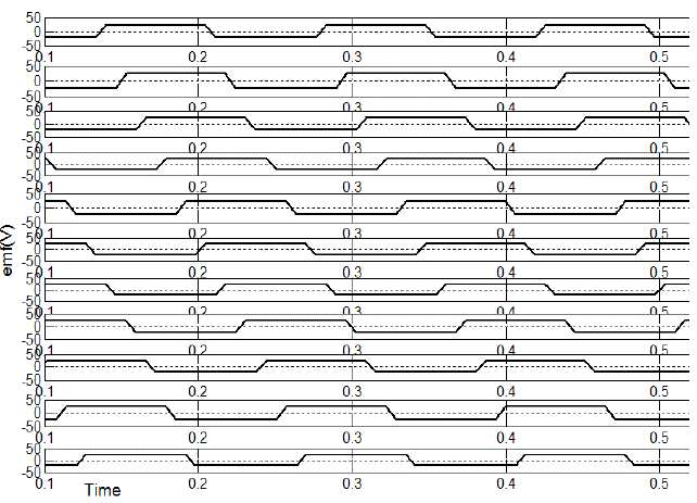
| The BLDC motor has a permanent magnet motor and stator windings are wound in such a way that the back electromotive Therefore no particular advantage in transforming the machine equation into well known two axis equations which are done in case of machines with sinusoidal back emf.[3]-[5] force is trapezoidal. The trapezoidal back emf shows that the mutual inductance between stator and rotor is not sinusoidal . |
MODELING OF ELEVEN PHASE BLDC
|
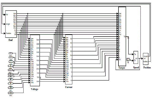
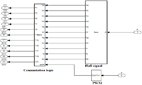
| The BLDC motor produces a trapezoidal back emf rectangular stator currents needed to produce constant torque. The overall system consist of BLDC motor, inverter block, Commutation logic block |
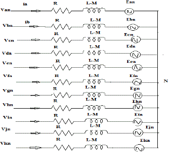
| The assumptions made for modelling 11 phase BLDC motor are magnetic saturation is neglected, Saliences of the poles are neglected, Hysteresis and eddy current losses are not considered, Self inductances, Mutal inductances and resistances of stator windings are equal. The stator voltage across phase a can be expressed as |
 |
 |
 |
| The stator currents are constrained to be balanced |
 |
| Thus voltage equation can be written as |
 |
| The equation of motion of a simple system with moment of inertia J, friction coefficient B and load torque Tl |
 (3) (3) |
| And electrical position and speed are related as |
 (4) (4) |
COMMUTATION LOGIC
|
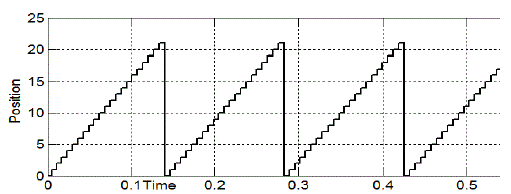
| The limitation of brush DC motor is replaced by BLDC motor, where electronic commutation is used. Electronic commutation is the way of distribution of PWM signal to the switches in the eleven phase BLDC motor. The sequence of distribution of gate signals depends on the feedback from BLDC motor. It also depends on the type of PWM signal (bipolar or unipolar). The position of rotor is sensed during every ïÃÂÃÂ/11 degrees. According to the position of rotor pulses to 22 switches, driving the BLDC motor is given. The commutation logic is developed by sensing the position of rotor. The position error is determined and compared with high frequency carrier which generates the PWM signal. After determining the position signals are generated which drive the BLDC motor. This model can generate exact square wave switching pattern. Thus generating signals for 22 switches. At each instant out of eleven phases 10 phases conduct, one phase remains unpowered. |
SPEED CONTROLLER
|
| The recommended compensation for speed control is PI compensation. The tuning of PI controller is done using Cohen coon method. |
SIMULATION RESULTS
|
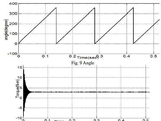
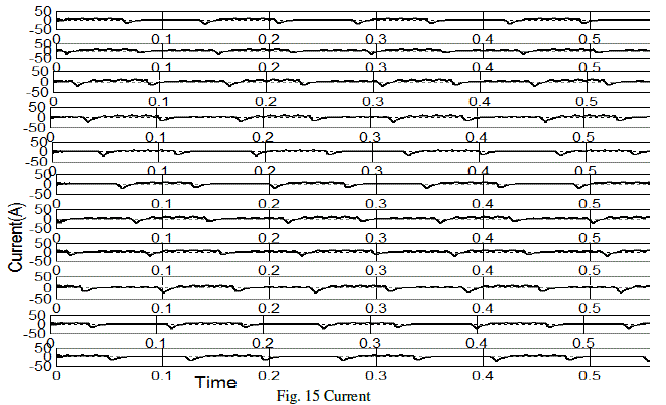
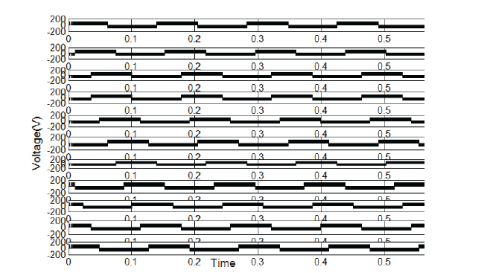
| The simulation of eleven phase BLDC is done and the results are presented. The parameters are P=4, R=0.7ïÃÂÃâ, M=1.5mH, L=2.72mH, Vdc=200V, J=0.002kgm2 , B=.002Nm/rad/sec |
CONCLUSION
|
| In this paper multiphase BLDC motor is designed. The simulation results of eleven phase BLDC motor are presented. Based on the mathematical model of eleven phase BLDC motor ,the modelling and simulation are studied. The simulation results shows it fit well for theoretical analysis also. The speed control of eleven phase BLDC motor is done. |
Tables at a glance
|
 |
| Table 1 |
|
Figures at a glance
|
 |
 |
 |
 |
 |
| Figure 1 |
Figure 2 |
Figure 3 |
Figure 4 |
Figure 5 |
 |
 |
 |
 |
 |
| Figure 6 |
Figure 7 |
Figure 8 |
Figure 9 |
Figure 10 |
 |
 |
 |
 |
| Figure 11 |
Figure 12 |
Figure 13 |
Figure 14 |
 |
 |
 |
| Figure 15 |
Figure 16 |
Figure 17 |
|
References
|
- MousaviS.M.H,Mirbaghere S M,Sefid S.S.S.G, “Simulation of New Multiphase BLDC motor Drive ”IEEE International conference on Powerelectronics Drives and Energy System 2012 PP 1-5
- T.Y Kim, B.K Lee, C.Y Won ”Modeling and Simulation of multiphase BLDC motor drive System for Autonomous under water vehicle” IEEEInternational Conference on Electric machines & drives” vol 2 may 2007 pp 1366-1371
- P Pillay and R Krishnan “Modelling and simulation and analysis of permanent magnet motor drives The brushless dc motor drive” IEEEtransactions on industry application vol 25 2 march april 1989 pp274-279
- P Pillay and R. Krishnan “ Application characteristics of permanent magnet synchronous and brushless dc motors for servo drives” IEEE TransIndApplvol 27 no 5, pp 986-996 sep/oct 1991
- P. Pillay and R. Krishnan, “Modeling of permanent magnet motor drives,”IEEETrans.Ind. Electron., vol. 35, no. 4, pp. 537–541, Nov. 1988.
- L. Parsa and H. Toliyat, “Fault-tolerant five-phase permanent magnet motor drives,” in Conf. Rec. IEEE IAS Annu. Meeting, Oct. 2004, pp.1048–1054. L. Parsa, “On advantages of multi-phase machines,” in Proc. IEEE Ind.Electron. Soc. Annu. Conf., Nov. 2005, pp. 1574–1579.
- L. Parsa and H. Toliyat, “Multi-phase permanent-magnet motor drives,” IEEE Trans. Ind. Appl., vol. 41, no. 1, pp. 30–37, Jan./Feb. 2005.
- L. Parsa, “On advantages of multi-phase machines,” in Proc. IEEE Ind.Electron. Soc. Annu. Conf., Nov. 2005, pp. 1574–1579.
- T. Gopalarathnam, H. A. Toliyat, and J. C. Moreira, “Multi-phase fault tolerant brushless DC motor drives,” in Conf. Rec. IEEE IAS Annu.Meeting, Oct. 2000, vol. 3, pp. 1683–1688.
- Dwari S, Parsa L “Fault tolerant control of five phase permanent magnet motor with trapezoidal back emf” IEEE transactions on industrialelectronicsvol 58 2011 pp 476-485
- X .Xiong, Q.Wu, Y. Rang, H.Li,L.Zhou Analysis and simulation of high power multiphase BLDC motor”International conference on artificialintelligence management science and electronic commerce 2011 pp 3751-3754.
- Anas S.R, Jaison H, Gopinath A, Namboothiripad M.N, Nandakumar M.P “Modeling and simulation analysis of redundant electromechanicalactuator bases servo system” International conference on comuter communication and electrical technology 2011 pp 358-363
- L. C. Chang, J. Muszynski, “Design of a 5-phase permanent magnet brushless DC motor for automobiles,” IEEE Conf. Vehicular Technology,vol. 5, 2003, pp.3197-3201.
- E. Levi, R. Bojoi, F. Profumo, H.A. Toliyat, S. Williamson, “Multiphase induction motor drives – a technology status review,” IET Electr.Power Appl., vol. 1, no.4, pp. 489-516, July 2007.
- S. Dwari and L. Parsa, “An optimal control technique for multiphase PM machines under open-circuit faults,” IEEE Trans. Ind. Electron., vol.55, no. 5, pp. 1988–1995, May 2008.
- D. Min, A. Keyhani, and T. Sebastian, “Fault analysis of a PM brushless DC motor using finite element method,” IEEE Trans. Energy Convers.,vol. 20, no. 1, pp. 1–6, Mar. 2005.
- E. Levi, “Multiphase electric machines for variable-speed applications,” IEEE Trans. Ind. Electron., vol. 55, no. 5, pp. 1893–1909, May 2008.
- K. T. Chau, C. C. Chan, and C. Liu, “Overview of permanent-magnetbrushless drives for electric and hybrid electric vehicles,” IEEE Trans. Ind.Electron., vol. 55, no. 6, pp. 2246–2257, Jun. 2008.
- R.Krishnan, Electric Motor Drives Modelling, Analysis and Control ©2001 Prentice Hall, India.
|