Keywords
|
| constant voltage charge, constant current charge, digital controlled charger, on-line ups system. |
INTRODUCTION
|
| Rechargeable batteries are extensively utilized in many applications. Since these appliances continuously consume electric energy, they need charging circuits for rechargeable batteries. Efficient charging shortens the charging time and extends the battery service life, while harmless charging prolongs the battery life cycle and achieves a low battery operating cost [2]-[4]. Moreover, the charging time and lifetime of the rechargeable battery depend strongly on the properties of the charger circuit. The Rechargeable batteries are vital to portable electronic equipment such as uninterrupted power supply, laptop, computers and cell phones. Fast charging circuits must be carefully designed and are highly dependent on the particular battery's chemistry. The most popular types of rechargeable batteries in use today are the Lead-Acid (LA), Nickel-Cadmium (NiCd), Nickel-Metal-Hydride (NiMH), and Lithium-Ion (Li-Ion). Lead-Acid (LA) is used in many portable applications because it is low cost and a low self-discharge characteristic. |
| The charging method is the process that dictates the method by which energy returned to the battery. If the energy is not returned to the battery in a way that it is compatible with the chemistry, the recharge can have detrimental effects on the battery. In the worst case, incorrect recharging can cause safety event (damage to equipment, personnel injury and environmental contamination).There are several generic charging methods Such as |
| 1. Constant current charging method |
| 2. Constant potential charging method |
| 3. Constant current and potential charging method |
| The constant potential charging is detrimental to NiCd sealed batteries, which exhibit a drop in voltage when the battery goes into overcharge and begins to heat up, causing the voltage to drop. This problem can be overcome by constant current charging method. Constant current charging is the simplest method of charging employing single low level current to the discharged battery. The current is set at a fixed rate that is usually selected at ten percent of the maximum rated capacity of the battery. Constant current charging is best suited for use on lead-acid batteries. The type of chargers usually small and relatively inexpensive. |
| o “Implementation and analysis of an improved series-loaded resonant DC-DC converter operating above resonance for battery chargers,” |
| The well-established advantages of resonant converters, including simplicity of circuit configuration, ease of the control scheme, low switching losses, and low electromagnetic interference, among others, have led to their attracting more interest. This work develops a highly efficient battery charger with an improved series-loaded resonant converter for renewable energy applications to improve the performance of traditional switching-mode charger circuits. The switching frequency of the improved series-loaded resonant battery charger was at continuous conduction mode. Circuit operation modes are determined from the conduction profiles. Operating equations and operating theory are also developed. This study utilizes the fundamental wave approximation and a battery equivalent circuit to simplify the circuit analyses [5]. |
| o “High-efficiency ZCS buck converter for rechargeable batteries” |
| In this paper zero-current-switching (ZCS) operation, this paper develops a novel soft-switching approach for rechargeable batteries. By inserting an auxiliary switch in series with a resonant capacitor, the proposed topology can obtain a novel ZCS buck dc–dc battery charger and significantly decrease the switching losses in active power switches. The proposed ZCS dc–dc battery charger has a straightforward structure, low cost, easy control, and high efficiency. The operating principles and design procedure of the proposed charger are thoroughly analyzed. The optimal values of the resonant components are computed by applying the characteristic curve and electric functions derived from the circuit configuration. Finally, a prototype charger circuit designed for a 12-V 48-Ah lead acid battery is constructed and tested to confirm the theoretical predictions. The maximum charging efficiency of the proposed topology during the overall charging period is too long [2]. |
| o “New digital-controlled technique for battery charger with constant currents and voltage control without current feedback |
| The main theme of this paper is to present a new digital-controlled technique for battery charger to achieve constant current and voltage control while not requiring current feedback. The basic idea is to achieve constant current charging control by limiting the duty cycle of charger. Therefore, the current feedback signal is not required and thereby reducing the cost of A/D converter, current sensor, and computation complexity required for current control. In this technique having some complex computation circuitry and the cost to be increased [1]. |
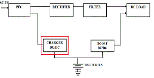
| Conventional battery chargers with linear power regulators can handle only particular power levels, have a critical circuit, and have a low power density. In ancient analog controlled batteries are build of resistors and capacitors where these components are depend on temperature variation and aging issues.[12], [13], [16]-[18]. Battery chargers require high quality, small size, light weight, and high energy conversions. But in the switch-mode operation subjects the control switches to high switching stress and high switching power losses. To maximize the performance of switchmode power electronic conversion systems, the switching frequency of the power semiconductor devices needs to be increased, but this results in increased switching losses and electromagnetic interference. But in proposed system rechargeable battery life is relation not only charger time. As for the recharging of lead-acid batteries, several types of chargers have been proposed with great success simple charger was first been constructed to deliver a constant voltage charge whereby the charge current is reduced to zero or trickle as the battery voltage rises [5]. However, this way of charging came with a non optimal charging profile, hence resulting in a long charging interval. Next, based on the close monitoring of battery current and voltage, some sophisticated chargers has suggested to employ high charge currents during the initial stage of charging cycle, then reduce gradually till the full electricity-charging is reached. But above techniques has some drawbacks. To overcome these problems a constant current charging method is proposed for UPS Systems [1]. Moreover, when the battery voltage is increased to the preset voltage level using constant current charge, the charger changes the control mode to constant voltage charge [1]. |
| Closed loop PI control is also provided to achieve the desired Output voltage. Pulse generators are employed to produce switching pulses and PWM. The output of the system can be viewed through the scope. |
DIGITAL-CONTROLLED CHARGER SYSTEM
|
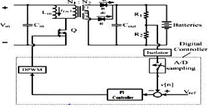
| Fig. 2 shows the digital controlled charger with constant current charging control method is proposed in this work. The basic idea is to keep constant current charging by limiting the duty cycle of charger [1]. Based upon the proposed constant current charging technique, a digital-controlled charger is designed and control method in software. |
| The PI and Digital Pulse width generation technique is used here [11]. PI controller calculates an "error" value as the difference between a measured process variable and a desired set point. The controller attempts to minimize the error by adjusting the process control inputs to achieve constant current and voltage charge. |
| The output is measured and the voltage and current measurement block measures the instantaneous voltage and current between two electric nodes. The output provides a Simulink signal that can be used by other Simulink blocks. The output of the system can be viewed through the scope. |
CONVERTER MODELLING
|
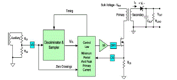
| The isolated flyback converter is a commonly-used converter for small power supplies such as battery chargers for portable devices and for auxiliary power supplies in electronic equipment. The control design of a flyback converter that provides three low-voltage DC output voltages from a single-phase mains source is explained. Fig.3 illustrates a simplified flyback convertor with the main voltage regulation blocks of the device shown. The power train operation is the same as any DCM flyback circuit but accurate output voltage and current sensing is the key to primaryside control. The flyback transformer is modelled using an ideal transformer with a magnetizing inductance in parallel. Leakage inductance is ignored because the model is intended for controller design and circuit level simulation rather than simulating the parasitic effects of components. The parameters of the flyback transformer are given in the Table 1. The output voltages of the open-loop flyback converter are heavily affected by the input DC voltage ripple. In order to regulate the output voltages, a current mode control scheme using a type 2 voltage controller to set the reference voltage is implemented [21]. |
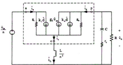
| The flyback converter in Fig.4 is composed of three stages. The power circuit to the secondary, the equivalent buck-boost converter, with the input voltage of Vin/n and inductance of L/n2, is obtained. Replacing the power MOSFET and diode in the equivalent buck-boost circuit by the small signal PWM switch models in DCM the small signal equivalent circuits are obtained as shown in Fig. 4 respectively. In the figures, the capital letters denote DC values and the caret the small-signal variation [21]. In the DCM circuit, gi = M2/R, ki = 2MV0/DR, gf = 2M/R, k0 = 2V0/DR and g0 = 1/R, where M = V0/Vin = nD(R / 2Lfs )1/2.D and fs are the duty cycle and switching frequency respectively. |
DIGITAL CONTROLLER DESIGN
|
| A proportional-integral controller (i.e., PI) with feedback can take the place of manual adjustment of the switching duty cycle to a DC-DC converter and act much more quickly than is possible “by hand.” The 89C51 was chosen for the controller use. It is inexpensive and can handle the entire voltage range. The best way to use this chip is in current-mode control. Many of the circuit parameters were determined according to the functionality of the chip. A voltage divider is placed across through the battery is used to sense the voltage and the output from the 89C51 is used as gate drive. The S-R latch is set initially by a short pulse from the clock causing the MOSFET to turn on. The current sense comparator tests the relationship between the voltage error signal and the sense resistor voltage. When the two signals match, the latch is reset and the switch turns off. This is peak current mode control as switch turn off point determines the peak inductor current. The voltage error signal is set and is used as reference for the maximum inductor current. Peak Current Mode Control determines the duty ratio of the switching action of the gate drive and regulates maximum current in system. An increase in the set reference voltage increases the duty ratio and current. An increase in input source voltage decreases the duty ratio without changing the output current. Fig.5. shows the block diagram of digital-controlled charger which includes MCU modulation gain, 1/VM, and voltage ratio of voltage feedback network, H, A/D sampling gain, and GADC. |
| Instead of the analog control, the DPWM control scheme chops the dc voltage during the voltage is greater than reference voltage. The PWM control keeps switching frequency constant and regulates duty-cycle to ensure the MOSFET turn on. |
| In this paper, the linear current control scheme, or synchronous PWM PI controller, is selected. The PI controller integrates the error between the feedback and reference voltage to generate a variable voltage which is then fed into the pulse-width modulator to produce the switching gate signal for MOSFET. Compared to Hysteresis controller, the PWM PI controller has some advantages below: 1) constant switching frequency; 2) closed-loop control; 3) good dynamic regulation; 4) low acoustic noise. PI compensator has been widely used in all types of the feedback system, especially for the systems originally containing a single pole. The constant current/constant voltage method is the most practical at present. The charging process of this method is consisted of two stages. First, the lead-acid battery is charged with constant current, so as to shorten the charging time. When the battery voltage reaches the required set value, it is charged with constant voltage. The charging current decreases gradually as the time extends, and the charger is cut off until the charging current decreases .The charging method used in this paper connects a DC/DC converter to the preceding stage output, so that the voltage and current of preceding stage maximum power control the constant current/constant voltage charge up method for lead acid battery. The constant current/constant voltage architecture is that the fed back output voltage uses a PI controller to control the duty cycle for charging. Since the PI controller can suppress high-frequency noise to improve the system or eliminate steady-state error, the battery output achieves stable constant current/constant voltage control. Take constant voltage as an example, the charging system uses state space averaging method to analyze the PI controller and DC/DC converter. |
RESULT AND DISCUSSION
|
| The fig. 6 shows the input voltage (vin) is 400v |
CONCLUSION
|
| A novel constant current charging control method for charger without current sensor is proposed. The analytical form for current and duty cycle relation is presented. The basic idea is to keep constant current charging by limiting the duty cycle of charger. Based upon the proposed constant current charging technique, a digital-controlled charger is designed and verified on a UPS prototype. A low-cost MCU is used to realize the proposed control method in software. The proposed digital-controlled charger has been applied to an on-line UPS prototype. Nowadays, rechargeable battery has been widely used in various kind of electronic device, such as portable devices, uninterrupted power supply (UPS) system, electrical vehicle, etc. Therefore, battery charger plays a very important role in recharging batteries efficiently and prolonging the battery life.Thus a battery charger is designed to get a constant current charging for UPS applications and the proposed topology is verified through simulation results. Through the simulation result, it can be applied to the renewable energy system and electrical vehicle using battery with high efficiency. |
Tables at a glance
|
 |
| Table 1 |
|
Figures at a glance
|
 |
 |
 |
 |
| Figure 1 |
Figure 2 |
Figure 3 |
Figure 4 |
 |
 |
 |
 |
| Figure 5 |
Figure 6 |
Figure 7 |
Figure 8 |
|
References
|
- Bo-Yuan Chen and Yen-Shin Lai, “New digital-controlled technique for battery charger with constant currents and voltage control withoutcurrent feedback” IEEE Trans. Ind. Electron., vol. 59, no. 3, pp. 1545-1553, mar.2012.
- Y. C. Chuang, “High-efficiency ZCS buck converter for rechargeable batteries,” IEEE Trans. Ind. Electron., vol. 57, no. 7, pp. 2463–2472,Jul. 2010.
- P. A. Cassani and S. S. Williamson, “Design, testing, and validation of a simplified control scheme for a novel plug-in hybrid electricvehicle battery cell equalizer,” IEEE Trans. Ind. Electron., vol. 57, no. 12, pp. 3956–3962, Dec. 2010.
- M. B. Camara, H. Gualous, F. Gustin, A. Berthon, and B. Dakyo, “dc/dc converter design for supercapacitor and battery powermanagement in hybrid vehicle applications-polynomial control strategy,” IEEE Trans. Ind. Electron., vol. 57, no. 2, pp. 587–597, Feb.2010.
- 5 ] Y. C. Chuang, Y. L. Ke, H. S. Chuang, and H. K. Chen, “Implementation and analysis of an improved series-loaded resonant DC-DCconverter operating above resonance for battery chargers,” IEEE Trans. Ind. Appl., vol. 45, no. 3, pp. 1052–1059, May/Jun. 2009.
- C. G. C. Branco, C. M. T. Cruz, R. P. Torrico-Bascopé, and F. L. M. Antunes, “A non-isolated single-phase UPS topology with 110 V/220 V input-output voltage ratings,” IEEE Trans. Ind. Electron., vol. 55, no. 8, pp. 2974–2983, Aug. 2008.
- G. Zanei, E. Cevenini, H. Ruff, and O. Ulibas, “Integrated systems for UPS: New solutions in the power quality chain,” in Proc. IEEE 29thInt.Telecommun. Energy Conf., 2007, pp. 582–586.
- L. A. Flores, O. Garcia, A. Roman, and M. S. Esparza, “Isolated DC-DC UPS based in a forward-forward converter analysis and design,”in Proc. IEEE 34th IECON, Nov. 2008, pp. 802–807.
- N. Vazquez, J. Villegas-Saucillo, C. Hernandez, E. Rodriguez, and J. Arau, “Two-stage uninterruptible power supply with high powerfactor,” IEEE Trans. Ind. Electron., vol. 55, no. 8, pp. 2954–2962, Aug. 2008.
- K. W. Ma and Y. S. Lee, “An integrated flyback converter for DC uninterrupted power supply,” IEEE Trans. Power Electron., vol. 11, no.2,pp. 318–327, Mar. 1996.
- F. Luo, Y. Kang, S. X. Duan, and X. L. Wei, “A novel digital controlled battery charger for high power UPS application,” in Proc.IEEE 5th Int. Power Electron. Motion Control Conf., 2006, pp. 1–5.
- L. Schuch, C. Rech, H. L. Hey, H. A. Grundling, H. Pinheiro, and J. R. Pinheiro, “Evaluation of a digital control system for a highefficiencybattery charger UPS,” in Proc. IEEE Int. Symp. Ind. Electron., 2003, pp. 956–961.
- G. J. M. de Sousa, C. M. T. Cruz, C. G. C. Branco, L. D. S. Bezerra, and R. P. Torrico-Bascope, “A low cost flyback-based high powerfactor battery charger for UPS applications,” in Proc. IEEE Brazilian Power Electron. Conf., 2009, pp. 783–790.
- E. Rodriguez, N. Vazquez, C. Hernandez, and J. Correa, “A novel AC UPS with high power factor and fast dynamic response,” IEEETrans. Ind. Electron., vol. 55, no. 8, pp. 2963–2973, Aug. 2008.
- A. Nasiri, N. Zhong, S. B. Bekiarov, and A. Emadi, “An on-line UPS system with power factor correction and electric isolation usingBIFRED converter,” IEEE Trans. Ind. Electron., vol. 55, no. 2, pp. 722–730, Feb. 2008.
- H. J. Chiu, L. W. Lin, P. L. Pan, and M. H. Tseng, “A novel rapid charger for lead-acid batteries with energy recovery,” IEEE Trans. PowerElectron., vol. 21, no. 3, pp. 640–647, May 2006.
- L. R. Chen, J. J. Chen, N. Y. Chu, and G. Y. Han, “Current-pumped battery charger,” IEEE Trans. Ind. Electron., vol. 55, no. 6, pp. 2482–2488, Jun. 2008.
- S. J. Chiang, H. J. Shieh, and M. C. Chen, “Modeling and control of PV charger system with SEPIC converter,” IEEE Trans. Ind. Electron.,vol. 56, no. 11, pp. 4344–4353, Nov. 2009.
- H. L. Chan, “A new battery model for use with battery energy storage systems and electric vehicles power systems,” in Proc. IEEE PowerEng. Soc. Winter Meeting, 2000, pp. 470–475.
- Y. H. Kim and H. D. Ha, “Design of interface circuits with electrical battery models,” IEEE Trans. Ind. Electron., vol. 44, no. 1, pp. 81–86,Feb. 1997.
- Dr. Johnschonbergerplexim GmbH, technoparkstraseel 8005 zurich “Modelling of current controlled flyback converter using PLECS”.
- L. O. Chua, C. A. Desoer, and E. S. Kuh, Linear and Nonlinear Circuits. New York: McGraw-Hill, 1987.
- R. Casanueva, C. Brañas, F. J. Azcondo, and F. J. Díaz, “Teaching resonant converters: Properties and applications for variable loads,”IEEE Trans. Ind. Electron., vol. 57, no. 10, pp. 3355–3363, Oct. 2010.
|