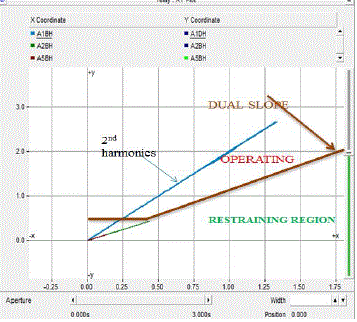
The differential protection of power transformer is a unit protection scheme. The protective scheme for power transformer should operate only for the internal fault, and it must be insensitive for any fault outside the zone of protection. That means the protection scheme should not operate for any external through fault and the magnetizing inrush current due to energization of the transformer under no load condition and also due to external fault removal. Transformer inrush currents are high-magnitude, harmonic-rich currents generated when transformer cores are driven into saturation during energization. These currents have undesirable effects, including potential damage or loss-of-life to the transformer, protective relay mal-operation and reduced power quality on the system. In power transformer differential protection second and fifth harmonics are analyzed using Fast Fourier Transform (FFT) technique to provide the dual slope differential relay operating chartrictics. The relay logic and the algorithm that uses fast fourier transform for extraction of fundamental and higher harmonics components of differential current which are used to block the Inrush current. The simulations were performed using PSCAD Simulation software. The proposed systems can be used to test new transformer differential protection algorithms and the actual differential relays available on the market.
Keywords |
| Differential protection of power transformers, Magnetizing inrush current, Fast Fourier Transform, harmonics,
PSCAD software |
INTRODUCTION |
| The basic operating principle of differential protection is to calculate the difference between the current entering and leaving
the protected zone. There is a phenomenon that occurred during removal of external through fault or due to energization of the
transformer under no load condition named magnetizing inrush current. The differential protection scheme should remain
insensitive for such magnetizing inrush current. The differential relay should not operate for the external/through fault. The
protective scheme should operate only for the internal fault, and it must be insensitive for any fault outside the zone of protection.
The protection operates when the differential current exceed the set bias threshold value. For external faults, the differential
current should be zero, but error caused by the CT saturation and CT ration error leads to non-zero value. To prevent
maloperation the operating threshold is raised by increasing the relay setting. Maloperation of the differential protection of power
transformer may occur due to Magnetizing inrush current, CT saturation and Through Fault Inrush. Among all these three;
magnetizing inrush results during excitation of Transformer under no load condition. It can also come in to picture during the
energization of parallel connected power transformer. For this setting of four relay parameter is very important. |
| IS1: The basic differential current setting |
| K1: The lower percentage bias setting |
| IS2: The bias current threshold setting |
| K2: The higher percentage bias setting |
| The tripping criteria can be formulated as: |
| Case 1 |
 |
| Case 2 |
 |
| Fast Fourier Transform technique is used for preventing the maloperation. The secondary current signals from the CTs are
sampled at a regular interval. This is an online Fast Fourier Transform (FFT), which can determine the harmonic magnitude and
phase of the input signal as a function of time. The input signals first sampled before they are decomposed into harmonic
constituents.Using the FFT technique to block the 2nd and 5th harmonics of the diffrential current to avoid mal-operation of
diffrential relay due to inrush current. |
MODELED SCHEMES FOR TESTING THE TRANSFORMER DIFFERENTIAL PROTECTION
ALGORITHMS |
| In [1] thesis there are presented the descriptions of simulation systems projects containing transformers and modeled
differential relays for their protection. These projects, made in the PSCAD software, reproduce the power transformers with
different vector groups and rated powers, lines (as PI-type two-terminal-pair networks), power source and the load on highervoltage
sides. For the modeled systems there are possibilities of switches control in both a manual and automatic (by simulating
differential relay) way. |
| In addition, depending on the transformer vector group and its rated power, there have been used proper algorithms for
appropriate operation of modeled transformer differential protection in simulation projects. The signals injected to the
differential relay may be brought from actual or ideal current transformers (depending on the requirements) |
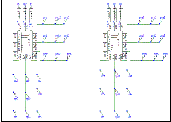
| Fig.1 shows the transformer differential protection system. The system containing two buses bus1 is connected to source and bus2
is connected to load and the transformer is connected between the buses. Breaker B1 and B2 connected both sides of transformer,
during internal faults the relay should trip the breakers.Ip1,Ip2, Ip3 and Is1 Is2, Is3 are the transformer primary and secondary line
currents. This currents are input signal of the relay logic block the output of relay logic block is trip signal that signal used to trip
the breaker. |
| In addition to the elements shown in the figure 1, in the simulation project there are blocks which contain the following
elements: |
| • elements of modeled differential relay, |
| • diagrams of analog signals (currents and voltages on higher- and lower-voltage sides of the transformer and signals
made available in the transformer model) and binary signals (states of switches), |
| • elements related to the control (choice of location and type of fault, breakers control, control of saving the
analog variables waveforms to COMTRADE-format file. |
| In all the modeled systems with transformers it is possible to visualize all the courses of currents and voltages on the higher
and lower-voltage sides and in the fault point. The observed voltage and current time-courses at relaying points, on the
secondary side of current and voltage transformers, can be saved as the COMTRADE format. |
| • internal and external single and multi-phase faults, with current transformers saturation absence and for various preload
of transformer (the impact of the appearance of non-periodic current component in fault current), |
| • metallic and resistive internal faults,various level of saturation of the CTs (on one or both sides of the transformer)
and various pre-load of transformer, in the case of external faults (whether there is no unnecessary pick-up of differential
function), |
| • external single-phase faults on the transformer side of a grounded star-point (whether there is no unnecessary pick- up
of differential function, and thus the differential function correctly eliminates the zero-sequence component of the
current) |
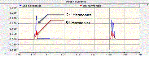
| • switching on (energizing) the unloaded transformer (whether there is no unnecessary pick-up of differential
function during the inrush of magnetizing current and appearance of a high content of 2nd harmonic in differential
current), |
| • transformer over-fluxing (whether there is no unnecessary pick-up of differential function due to the large rise of supply
voltage and the emergence of a high content of 5th harmonic in the differential current). |
A SCHEME OF MODELED TRANSFORMER DIFFERENTIAL PROTECTION` |
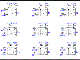
| The protection modeling process has been focused on protection operation logic, not on digital signal processing in order
to computing the 1st, 2nd and 5th harmonics of phase currents. For the calculation of particular harmonics of phase currents (phasors), the On-Line Frequency Scanner module (from PSCAD/EMTDC Master Library, [3]) has been used. The
description of direct calculation method for measurement signals (current phasors), without using the On-Line Frequency
Scanner module, may be found in [2]. Fig. 1 shows the location of differential relay model in the simulation project. Example
of implementation in PSCAD software of the modelled relay. To build a simulation model of differential relay, there were used
ready-to-use modules from PSCAD Master Library such as: |
| • logic gates, timers, summing/difference junctions, multipliers, dividers, |
| • module which can determine the harmonic magnitude and phase of the input signal as a function of time (On-Line
Frequency Scanner), |
| • modules from the Relays (Dual Slope Current Differential Relay, Over current detection block). |
| Algorithms of elements for elimination of the zero-sequence current and for vector group adaptation, was written using a
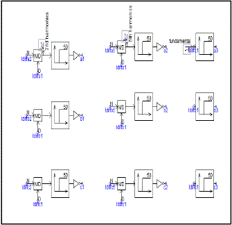
programming language Fortran.The modeled relay consists of (Fig. 3): |
| • the amplitude adjustment of the lower- (LV) and higher- voltage (HV) power transformer side. |
| • systems to eliminate zero-sequence current symmetrical component on the higher-voltage transformer side (grounded
transformer windings connected in star): mathematically or using current from the transformer star point. |
| • adaptation to vector group made on the lower-voltage transformer side. |
| • transformation of instantaneous current values (the upper- and lower-voltage transformer sides) to a phasor (amplitude
and phase separation) for harmonic 1st, 2nd and 5th. |
| • calculation of the differential currents (Idiff) and stabilized currents (Ibias) for the 1st harmonic currents of phases A, B,
C, and checking the performance criteria for each phase, i.e., whether the point of the calculated currents Idiff and
Ibias are above the operating characteristics Idiff = f(Ibias) of the relay. |
| • calculation of the differential currents (Idiff) for 2nd and 5th harmonic currents of phases A, B, C, and checking the
performance criteria for each phase, i.e. whether the differential currents calculated 2nd and 5th harmonic with respect
to the corresponding differential currents 1st harmonic exceeds the set threshold. |
| • checking whether the current differential 1st harmonics for each phase exceeds the set threshold, i.e. checking the
performance criteria of non-stabilized differential relay function. |
| • checking the performance criteria of the stabilized differential function for at least one of the three phases (calculated
diffrential first harmonic current are in the area of operation for stablized characteristics of relay, the content of the 2nd
and 5th harmonic does not exceed the threshold values), and the verification of the performance criteria for the nonstabilized
differential at least one of the three phases and sending an impulse to open breakers signal (signal T) on the
higher- and lower-voltage transformer side . |
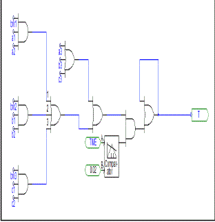
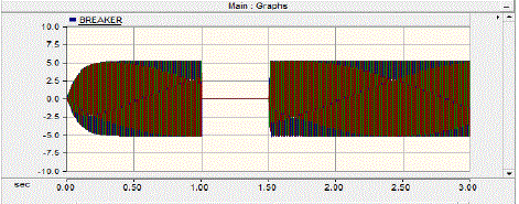
| From fig 5 brk1, brk2, brk3, a1, a2, a3, b1, b2, b3, c1 ,c2 ,c3 denotes the output signals from the relay(Fig. 3.) and the signal
values are 0 and 1 is given to AND gate. (Fig. 4.) checking the performance criteria of the stabilized differential function for at least
one of the three phases (calculated differential 1st harmonic currents are in the area of operation for stabilized characteristics of
relay, the content of the 2nd and 5th harmonic does not exceed the threshold values), and the verification of the performance
criteria for the non-stabilized differential at least one of the three phases and sending an impulse to open breakers. Breaker
operation is considering 0 and 1.Figure 5 shows the value 1 denoted the breaker is ON position and 0 denoted the breaker closed
position. When trip signal given from the relay. Instantaneously breaker open position 1 and after the fault clear suddenly breaker
closed 0. |
EXAMPLE RESULTS OF FUNCTIONAL PERFORMANCE TESTS FOR MODELED DIFFERENTIAL
PROTECTION |
| A. Short Circuit,A- B-C Metallic Type (Internal on HV Transformer Side) |
| This section presents selected results of disturbance simulations for modeled test schemes. The research, described
in greater detail in [1], have been aimed to monitor and analyze the signals that occur during chosen disturbances related to
transformers and to verify the operation of modeled transformer differential protection. |
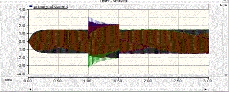
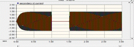
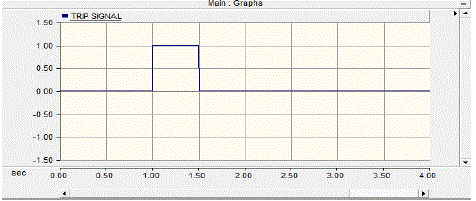
| During fault condition the relay gives trip signal to the breaker at the instant the breaker should be opened current flowing
through the breaker is zero.After clearing the fault the breaker becomes closed. (fault occurred at 1.0 sec, duration of fault 0.5 sec). |
| B. switching ON the un loaded transformer |
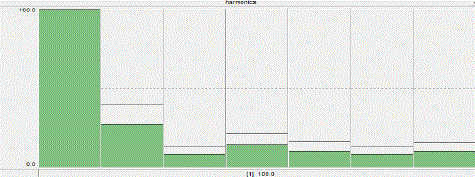
| Fig. 11 shows the waveforms of differential currents and stabilized currents (per phase) with a frequency of 1st (fundamental)
harmonic. They show that the differential currents are larger than the corresponding stabilized currents. If the differential
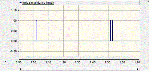
(stabilized) function is not blocked in the analyzed case it comes to unwanted operation of the differential relay. Evidence of this
change is status of output trip signals (brk 1, brk 6 and brk 7) coming from all phases (with leading logical zeros to logical ones)
when switching the unloaded transformer on - as shown in Fig. 12. This is also evident transition the currents through the
operation characteristics of the modeled relay. |
SUMMARY |
| The PSCAD/EMTDC software can be successfully used to modeling the disturbances in schemes with transformers and
differential relays protecting transformer from effects of this disturbances occurrence. There can be created the simulation
projects of schemes with power transformers, which allow to analyze various types of disturbances that may occur in this
schemes, such as internal and external faults, switching on the unloaded transformers, voltage spikes on the transformer terminals,
faults with current transformer saturation, etc. A lot of tests have been made for modeled test schemes. Example results of the
tests, described in the article, have shown the usefulness of PSCAD/EMTDC for verifying the operation correctness of
differential protections for power transformers. It is important that the calculations are in this program performed in the time
domain. Thanks to this, instantaneous values of phase voltages and currents may be injected into the modeled protection device.
Modeled in the thesis [1] test schemes can be used for testing the protection algorithms of real protection devices (thanks to the
possibility of saving the waveforms of analog and binary signal to COMTRADE files) and for designing the new differential
protection solutions. Also modeled in the thesis [1] differential relays, for protecting power transformers of different rated powers
and different vector groups, and example tests results of its operating have proved that PSCAD/EMTDC can also be used for
testing new protection function algorithms and verifying operating correctness of the existing algorithms (e.g. for educational or
training purposes). |
Figures at a glance |
 |
 |
 |
 |
 |
| Figure 1 |
Figure 2 |
Figure 3 |
Figure 4 |
Figure 5 |
 |
 |
 |
 |
 |
| Figure 6 |
Figure 7 |
Figure 8 |
Figure 9 |
Figure 10 |
 |
 |
 |
| Figure 11 |
Figure 12 |
Figure 13 |
|
References |
- K.Pyrzak, Application of PSCAD/ETMDC software for modeling of transformers and differential protective relays, The MSc thesis, (in Polish), Warsaw2011.
- M.Sztykiel, C.L. Bak, Line Differential Protection Scheme Modelling for Underground 420 kV Cable Systems, EMTDC/PSCAD Relays Modeling,OMICRON electronics, International Protection Testing Symposium (IPTS), Brand 2011
- Manitoba HVDC Research Centre, PSCAD v.4.2.1 Online Help
- CIGRE: Analysis and guidelines for testing numerical protection schemes, CIGRE Report No 159, Working Group 34.10, August 2000.
- A Guzman and S.Zocholl ― A current based solution for transformer differential protection – part 1:Problem Statement‖ ,‖ IEEE Trans. Power Delivery,volume 16, 2001.
- A.M. Guzman and S. Zocholl, ―Performannce analysis of traditional and improved transformer differential protective relays‖
- B.Kasztenny and M.Kezunovic, ―Improved Power Transformer Protection Using Numerical Relays‖, IEEE Computer Applications in Power, Vol.11, No.4,October 1998.
- B.Gladstone and M van der Veen ―Transformer Based Solutions to Power Quality Problems‖ Power System World, 2001.
- C. D. Hayward, ―Harmonic-Current-Restrained Relays for Transformer Differential Protection,‖ AIEE Transactions, Vol. 60, 1941.
- C. A. Mathews, ―An Improved Transformer Differential Relay,‖ AIEE Transactions, Vol. 73, Part III, June 1954.
- C. H. Einval and J. R. Linders, ―A Three-Phase Differential Relay for Transformer Protection,‖ IEEE Transactions PAS, Vol, No. 6, Nov/Dec 1975.
- J. Lewis Blackburn, ―Protective Relaying,‖ Marcel Dekker Inc., 1987.
- J. H. Brunke, J.K. Froehlich, "Elimination of Transformer Inrush Currents byControlled Switching, "IEEE Transactions On Power Delivery, vol. 16, no. 2, April 2001.
- K.Karsai, D.Kerenyi and L. Kiss , ―Large power transformers‖, Elsevier, New York, 1987.
- L F. Kennedy and C. D. Hayward, ―Harmonic-Current-Restrained Relays for Differential Protection,‖ AIEE Transactions, Vol. 57, May 1938.
- M.Manana, S. Perez and G. Renedo ― Effects of Magnetizing Inrush Current
- P.E. Sutherland ―Application of transformer ground differential protection relays , IEEE Trans. Power Delivery, volume 36, 2000.
|