Power system harmonics and oscillations are an inevitable phenomenon of the electrical system. Faults protection relaying operation can cause the oscillation to collapse the system. In order to damp these power system oscillations, different control methods and different devices are used. Flexible ac transmission systems (FACTS) technology is the newest way of improving power system operation controllability and power transfer limits which has been added in the stream with the progress in the field of power electronics devices. A number of researches had been done to find out the control schemes for performing the oscillation-damping task of UPFC. Here we propose a method based on Model predictive control (MPC) and using Bacterial Forging Algorithm (BFA) for modeling Unified Power Flow Controller. Modeling of UPFC is designed with its unique capability to control simultaneously real and reactive power flows on a transmission line as well as to regulate voltage at the bus where it is connected. Therefore this device create a remarkable quality impact on power system stability. UPFC with additional PI controller is used along with the UPFC main controller for this purpose. The simulation is carried out in MATLAB/simulink which shows promising results.
Keywords |
| Flexible ac transmission systems, Unified Power Flow Controller, Model predictive control, Bacterial
Forging Algorithm. |
INTRODUCTION |
| With the growing demand of electricity, at times, it is impossible to erect new lines to face the situation. FACTS
make use of the thyristor controlled devices and optimally utilize the existing transmission network. FACTS are highpower
electronics-based devices capable of altering voltage, phase angle, and impedance at particular points in power
systems. Their fast response offers high-power stability enhancement, therefore preventing possible voltage collapse.
UPFC is the second generation of FACTS devices that is able to provide series and shunt compensations in
transmission systems . Within its operating limits, a UPFC can independently control three power system
parameters. |
| Since the proposal of the UPFC, there has been increasing interest in finding a suitable control method to
suit a range of system operating conditions. Various controllers have been proposed to regulate the operation of
UPFC. UPFC for damping power system oscillations an additional PI controller is used along with the UPFC main
controller for this purpose. Modeling is achieved in this project by implementing Model Predictive Control Technique
and Bacterial Foraging Algorithm. The simulation is carried out in MATLAB/simulink which shows promising results.
This is caused by the control parameters being determined based on certain system conditions. |
UNIFIED POWER FLOW CONTROLLER |
UPFC Operation |
| The FACT type of controller is used to optimize the power flow in their transmission system. The UPFC is a device
which can control simultaneously all three parameters of line power flow (line impedance, voltage and phase angle). It
is a one of the FACTS family that used to optimum power flow in transmission system. The UPFC is a combination of
static synchronous compensator (STATCOM) and static synchronous series compensator (SSSC). Besides that the
UPFC also provides an additional flexibility by combining some of the function above. UPFC can also have a unique capability to control real and reactive power flow simultaneously on a transmission system as well as to regulate the
voltage at the bus where it’s connected. The UPFC also can increase the capability of the power flow to the load
demand until its reach its limit in the short period. At the same time the UPFC also can increase the security system by
increase the limit of transient stability, faulty and the over load demand. Lastly the UPFC also can reduce the value of
the reactive power and will optimum the real power flow through the transmission line. |
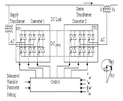
| The schematic description of UPFC is shown in Figure 1. These two types of converter are from the voltage sourced
converter (VSC) that implement based on the concept of the solid state synchronous voltages source (SVS). It’s
consists two VSC with a common dc link. This converter consist the six valve of a gate-turn-on (GTO) parallel with the
reverse diode and dc capacitor. An AC voltage is generated from a DC voltage through sequence switching of the
GTOs. The DC voltage is unipolar and the DC current can flow freely in either direction. By control the angle of the
converter output voltage will control the real power exchange between converter and the AC system. If the output
voltage of converter is control to lead the AC system voltage the power flow is from direction DC to AC side (rectifier)
whereas if the control is lag the AC system voltage the power flow is in the inverter condition. |
UPFC Operating modes |
| The UPFC has many possible operating modes. First is VAR Control Mode where the reference input is inductive
or capacitive VAR request. The shunt converter control translates the var reference into a corresponding shunt current
request and adjusts gating of the converter to establish the desired current. For this mode of control a feedback signal
represent the dc bus voltage, Vdc is also required. Then the second is Automatic Voltage Control Mode whereas the
shunt reactive current is automatically regulated to maintain the transmission line at the point of the connection to a
reference value. For this mode of control, voltage feedback signals are obtain from the sending end bus feeding the
shunt coupling transformer. The structure of UPFC with its shunt and series inverters offers great flexibility in
controlling all power transfer parameters (transmission voltage, transmission impedance, and transmission phase
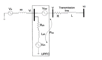
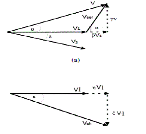
angle). A simple transmission system including UPFC is explained with the Figure 2. The UPFC vector diagrams for
the series inverter and the shunt inverter are shown in the Figure 3. |
| This flexibility is due to the ability of the shunt and series inverters of generating output voltages with
controllable magnitude and angle which provide the possibility of many operating modes. The general operating
modes are to have the shunt inverter operated in automatic voltage control mode and the series inverter to be
in automatic power flow control mode. The shunt inverter is operated to absorb or generate reactive power to
regulate the bus voltage at which UPFC is connected. The series inverter operating mode depends on the relative
phase angle and magnitude of the injected voltage, and they are controlled maintain or vary active and reactive
power flow through the transmission line within a predetermined region. |
CONTROLLER DESIGN AND LINEARIZATION PROCESS |
| To operate the UPFC in the automatic control mode and also to use the UPFC to enhance power system stability
and damp low frequency oscillations, two control designs need to be performed. A primary control design, referred to
as the UPFC basic control design, involves simultaneous control of (i) real and reactive power flow on the transmission
line, (ii) sending bus voltage magnitude, and (iii) DC voltage magnitude. A secondary control design, referred to as the
damping controller design, is a supplementary control loop that is designed to improve transient stability of the entire
electric power system. |
| The m-files added to the PST form the state matrices of a power system model including a UPFC with the DC-link
voltage as state. The basic control of the UPFC based on PI-controllers for the real and reactive line power flow, the
sending bus voltage, and the DC-link voltage, as well as a double-stage lead-lag compensator with a washout can be
included in the linearization process. |
TECHNICAL IMPLEMENTATION |
Model Predictive Controller Design |
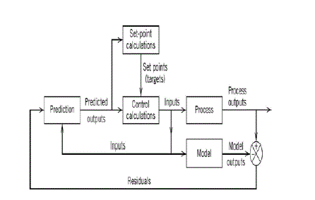
| MPC is based on iterative, finite horizon optimization of a plant model. The basic block diagram of MPC is shown
in the Figure 4. At time t the current plant state is sampled and a cost minimizing control strategy is computed (via a numerical minimization algorithm) for a relatively short time horizon in the future t, T + t Specifically, an online or onthe-
fly calculation is used to explore state trajectories that emanate from the current state. The prediction horizon keeps
being shifted forward and for this reason MPC is also called receding horizon control. Although this approach is not
optimal, in practice it has given very good results. Much academic research has been done to find fast methods of
solution of Euler-Lagrange type equations, to understand the global stability properties of MPC's local optimization,
and in general to improve the MPC method. |
| Model Predictive Control (MPC) is a multivariable control algorithm that uses: |
| • An internal dynamic model of the process |
| • A history of past control moves and |
| • An optimization cost function J over the receding prediction horizon, to calculate the optimum control
moves. |
| The optimization cost function is given by: |
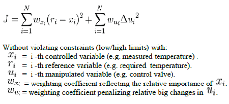 |
| Model predictive control techniques include a number of design parameters: |
| N : Model horizon |
| T : Sampling period |
| P : Prediction horizon (number of predictions) |
| M : control horizon (number of control moves) |
| Q : weighted matrix for predicted moves (Q > 0) |
| R : weighted matrix for control moves (R > 0) |
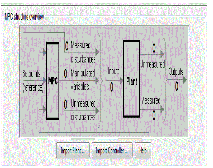
| MPC structural overview is shown in the Figure 5. The following are the steps for linearization of the palnt: |
| a. Launching the control and estimation tools manager. |
| b. Constructing specifications for the equilibrium operating point |
| c. Finding the operating point |
| d. Linearizing the point |
| e. Building MPC controller. |
Bacterial foraging Method |
| Bacterial foraging algorithm (BFA) is the form of foraging algorithm which keeps all the features of the BF
optimization and also keeps all advantages of BF. It enhances the exploration capability and also the diversity of search
process of BF. BF algorithm is an efficient population based stochastic search technique. The idea of BF algorithm is
based on the foraging mechanism of E. coli bacteria that are present in human intestines. The control system of these
bacteria that dictates how foraging should proceed can be subdivided into four sections namely Swarming and tumbling
via flagella, Chemotaxis, Reproduction and Elimination and Dispersal. |
| BF algorithm is an efficient population based stochastic search technique recently developed by Kevin M. Passino
(2002) which was published in IEEE control system Magazine. BF has found an increasing interest in the recent years
as an optimization technique due to its high ability to search the promising areas of the solution space. The idea of BF
algorithm is based on the foraging mechanism of E. coli bacteria that are present in human intestines. Natural selection
tends to eliminate animals with poor foraging strategies and favour the propagation of genes of those animals that have
successful foraging strategies since they are more likely to enjoy reproductive success. After many generations, poor
foraging strategies are either eliminated or shaped into good ones. The E. coli bacteria that are present in our intestines
also undergo a foraging strategy. |
| Contributions of this thesis can be summarized as follows: A new stochastic search technique, named bacterial
foraging (BF) method, is proposed. New search mechanisms and evolution procedures are incorporated into the
classical BF. The proposed BFA is mainly to enhance its exploration capability, search diversity and convergence
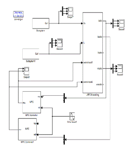
behavior. The Bacterial Foraging Algorithm has been formulated for the solution of power flow problems. For this
purpose, decision variables of the problem are coded and objective function and constraints of UPFC are modeled
within the proposed BFA as shown in the Figure 6. |
| Exploration and exploitation capabilities are two important aspects for a stochastic search technique. Exploration is
the algorithm’s ability to cover and explore different areas in the feasible search space and exploitation, is the ability to
concentrate only on promising areas in the search space and to enhance the quality of the potential solution in the
promising region. BF algorithm has high exploitation capability due to its swarming behavior and nested loops. To
solve nonlinear Power Flow problem with complex solution space, the stochastic search technique should also have
high exploration capability to search different areas of the solution space. For this, a new version of BF algorithm, is
presented to enhance the exploration capability and diversity of the search process of BF, such that it can obtain good
solutions for complex optimization problems. |
SIMULATION RESULTS |
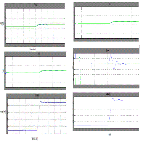
| The actual inputs for the UPFC model contains harmonics in voltage and current. The output we obtained from the
linearization of UPFC model will be free from harmonics and oscillations. Thus the systems response for different
types of short circuit levels is obtained which is described with the help of the Figure 7. |
CONCLUSION |
| This paper explains how Bacterial foraging algorithm (BFA) to solve multi objective comprehensive model of
optimal power harmonic elimination problems along with the model predictive control technique. BF has high local
search and exploitation capabilities due to the swarming behaviour of the bacteria and the nested loops. New operators
and procedures have been designed in this research work to enhance search diversity, exploration capability and
convergence behaviour of BF. It analyse UPFC steady-state, dynamic and linearized models, bacterial foraging
algorithm and Model Predictive Control technique for interfacing the UPFC with the power network and UPFC’s basic
and damping controller design. The overall multi-objective solution effectively treated with proposed Bacterial
Foraging Algorithm is tested with various IEEE standard systems. This feature cannot be accomplished with the
mechanical and other FACTS devices, only the UPFC can be used for voltage support and for improvement of transient
stability of the entire electric power through a supplementary control loop. Simulation results have shown that
controller exhibits good damping characteristics for different operating conditions and compared to the conventional
controller shows superior performance. |
Figures at a glance |
 |
 |
 |
 |
| Figure 1 |
Figure 2 |
Figure 3 |
Figure 4 |
 |
 |
 |
| Figure 5 |
Figure 6 |
Figure 7 |
|
References |
- N. G. Hingorani and L. Gyugyi, “Understanding FACTS”, IEEE Press, 1999.
- John J paserba, “How FACTS controllers benefits ac transmission system”.
- J. Pourhossein, G. B. Gharehpetian, and S. H. Fathi, “Unified Interphase Power Controller (UIPC) Modeling and Its Comparison With IPC and UPFC,” IEEE transactions on power delivery, vol. 27, no. 4, October 2012.
- Kalyan K. Sen, E Eric J. Stacey, “UPFC - Unified Power Flow Controller: Theory, Modeling, and Applications”, IEEE Transactions on Power Delivery, Vol. 13, No. 4, October 1998.
- Su-ping Pei, Yu-guo Chen, “The Control and Compensation Strategy Research of Unified Power Quality conditioner”, IEEE transactions on power systems 2011.
- P. Papic, D. Povh and M. Weinhold, “Basic control of unified power flow controller”, IEEE Trans. Power Syst., vol. 12, no. 4, pp. 1734–1739, Nov. 1997.
- H. Fujita, Y. Watanabe, and H. Akagi, “Control and analysis of a unified power flow controller”, IEEE Trans. Power Electron., vol. 14,no. 6, pp. 1021–1127, 1999.
- Xia Jiang, Joe H. Chow, Abdel-AtyEdris, Bruce Fardanesh, and EdvinaUzunovic, “Transfer Path Stability Enhancement by Voltage- Sourced Converter-Based FACTS Controllers”, IEEE transactions on Power delivery, vol. 25, no. 2, April 2010.
- Tang W. J., Li M. S., Wu Q. H. and Saunders J. R., “Bacterial Foraging Algorithm for Optimal Power Flow in Dynamic Environments”, IEEE transactions on circuits and system Vol. 55, No. 8, pp.345-353, 2008.
- Tripathy M. and Mishra S. , “Bacteria foraging-based solution to optimize both real power loss and voltage stability limit”, IEEE rans. Power Syst., Vol. 22, No. 1, pp. 240–248, 2007.
- Vahedi H., Hosseini S. H. and Noroozian R., “Bacterial Foraging Algorithm for Security Constrained Optimal Power Flow”, IEEE Transactions on Power Systems,Vol.41,No. 1, pp. 1-6, 2010.
- Peterson N. M., Tinney W. F. &Bree D. W., L. Gyugyi and N. Hingorani, “Understanding FACTS: Concepts and Technology of Flexible AC Transmission Systems”, Piscataway, NJ: IEEE Press, 2000.
|