Keywords
|
| Synchronous Generator model development,Exciter, Controller, Satiability, etc |
INTRODUCTION
|
| An excitation controller sets an output terminal reference voltage of a synchronous machine from reactive power output from the synchronous machine and a high side reference voltage of a transformer , and controls the field current to be supplied to the field winding of the synchronous machine in response to the deviation between the reference voltage and the output terminal voltage. This makes it possible to solve a problem of a conventional excitation controller in that although it can maintain the transmission voltage on the transmission bus at a fixed value, an expensive proportional-plus-integral-plus derivative controller is needed for detecting the transmission voltage on the transmission bus, which increases the manufacturing cost of the excitation controller.Synchronous generators are exclusively used for electrical power generation. The generator is supplied with real power from a prime mover, usually a turbine, whilst the excitation current power system as a source of electrical is provided by the excitation system. |
| A design of such an excitation system should also be satisfactory for a wide range of operating conditions as well as for fault conditions. Practical methods for nonlinear control include an open-loop inverse model of the nonlinear plant dynamics and the use of feedback loops to cancel the plant nonlinearities. The approximation of a non-linear system with a linearized model yields to the application of adaptive control, where real-time measurements of the plant inputs are used, either to derive explicitly the plant model or design a controller based on this model (indirect adaptive control), or to directly modify the controller output (direct adaptive control). Typical studies concerning applications of modern algebraic and optimal control methods in excitation controller design using linear system model.In general, excitation control systems for synchronous machines have a basic function to perform automatic voltage regulation functions so as to control a terminal voltage of the synchronous generator to be constant, with ancillary functions being an over excitation limit function and an under excitation limit function so that the operation of the synchronous machine is stable and within the critical limits. In the area of synchronous generator excitation control Kanniah, Malik, Hope et al. [1] in power system operation is towards computerized control and management .One class of digital adaptive regulators called self-tuning regulators is suitable for this purpose. In synchronous generator control a conflict arises between the small sampling interval necessary to track the dynamics and large computation time required by the process computer. Mao, C. Fan, J et al. [2] they the use of an adaptive optimal control algorithm for two real-time control applications, an optimal excitation control of a synchronous generator (OEC) and a power system stabilizer (PSS), is described. Experimental studies on a physical model of a power system showed that the proposed optimal excitation control (OEC) and power system stabilizer (PSS) can track the controlled system by parameter identification at different operating conditions. The proposed algorithm is based on linear optimal control theory. The proposed OEC and PSS can track the controlled system very rapidly. Flynn, D.Brown and M.D et al. [3] studies have suggested a number of strategies to deal automatically with plant nonlinearities and plant ageing, perhaps the most significant of which is adaptive control. These methods can improve overall control of turbo generator systems. Power system control essentially requires a continuous balance between electrical generation and a varying load demand, while maintaining system frequency, voltage levels and network security.Deghdy, S. Yousef, H. Ahmed et al. [4] a poleplacement adaptive self-tuning regulator is proposed for the design of digital power system stabilizers. The proposed technique employs a self-timing pole-placement power system stabilizer in order to improve the dynamic performance of a synchronous machine under a wide range of operating conditions. |
EXCITATION SYSTEM MODEL AND REACTIVE POWER REGULATION
|
| Most generators are equipped with an AVR. These devices maintain the terminal voltage of the generator at a specified value by modulating the field voltage and hence the field current to supply the required reactive power to the load. However, as a distributed generation, the voltage regulation is prohibited by IEEE 1547, unless special agreements are made. A common operation mode for the reactive power (or power factor) regulation. |
| The exciter systems widely used for synchronous machines are commonly subdivided into the four different categories. For simplicity of analysis in the time frame involved, the excitation system here is represented as a tuned PI controller with a necessary lag circuit. The parameters of the circuit model are approximated from the aggregate response of terminal voltage of a generator. Fig.3 shows the model of the excitation system used for the machine simulation. A feedback PI controller is cascaded with the exciter to regulate the reactive power of the machine. Therefore, when the grid is connected, the reactive power output of the machine will follow the desired reference value. |
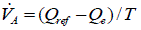
| The description of the reactive power regulator and the exciter is given by |
 |
 |
 |
| Where,VA andVB are the intermediate variables indicated in above Fig-1. |
| K1, K2 and K3 are constant in the controller. |
| T1 ,T2and T3 are time constant in the controller. |
| Q ref is the reference value of the reactive power. |
| Vref is the reference for the terminal voltage. |
| Vt is the terminal voltage of the efd is the field voltage as the input to the generator |
PI CONTROLLER
|
| The PI controller computes and transfers a signal which is desired to the controlled.The output signal O(t)iscomputed. The PI controller depends on the parameters is proportionalgain(Kp),integral time(Ti),output signal O(t),error e(t) and etc.The change to the output of proportional gain Kpi.e the proportional to the current error value. Theproportional gain Kp value is high the system become unstable. On the other hand a small value is given of the Kp, asmall output response is obtained. The PI controller eliminates its steady state error.The advantages of PI controller isdesign is simple, and fast response,improves the steady state response.In the PI controller is obtained by Kp,Ki,values. The disadvantages of PI controller is eliminates its steady state error and peak over shoot. |
MODELING OF THE POWER-VOLTAGE GENERATING SYSTEM
|
| A block-oriented third-order model of the generator connected to an infinitely strong grid follows with a few assumptions, from the linearization to the Park equations for a three-phase synchronous machine in a given operating point. In Fig.3 this third-order generator model is extended with the speed control loop, including the approximated steam valve transfer and turbine transfer functions and with the voltage regulator.In an interconnected power system, load frequency control (LFC) and automatic voltage regulator (AVR) equipment is installed for each generator. The controllers are set for particular operating condition and take care of small changes in load demand to maintain the frequency and voltage magnitude within the specified limits. Small changes in real power are mainly dependent on changes in rotor angle δ and, thus, the frequency. The reactive power is mainly dependent on the voltage magnitude i.e., on the generator excitation. The excitation system time constant is much smaller then the prime mover time constant and its transient decay much faster and does not affect the LFC dynamic. So the cross-coupling between the LFC loop and the AVR loop is negligible, and the load frequency and excitation voltage control are analysed independently. |
| The parameterization of this model is realized by full-scale measurement in the power station. These measurements are carried out by applying the following stepwise disturbances to the unit 2.5 and 5 precent stepwise variations in the set point of the steam valve, i.e., the power set point, while the value (power-feedback loop open). 2.5 and 5 precent stepwise variations in the voltage set point while the steam valve is maintained at constant value. |
| These measurements are done at various operating points; the result on two operating points, namely an inductive point 150MW/60MVR and a capacitive point 100/-10MVR, are shown in this note. At the same time two values of the gain in the voltage-control loop are used and a separate set of measurements is performed to cheek the influence of the instrumented current feedback on the stability. |
| The results of the modelling and identification lead to the following conclusions. |
| 1. The ninth-order model of the unit reasonably resembles the measured behaviour. |
| 2. An elementary analysis of the data leads to the conclusion that the contribution of the primary control loop to the dynamic behaviour of the generator system can be neglected. |
| 3. For the different operating point and taking into account the observed variation in the ofKi’s, the s-plane configuration of the present-day system. |
RESULT AND DISCUSSION
|
A)Here use PI and PID controller for output steady state signal control.
|
| In the above fig4 Generator voltagevs. time is shown. In Fig-4athe PI controller is used and Fig.4b the PID controller is used. The damping oscillation is 4s in case of PI controller and 1.2s in case of PID controller.The result is better in PID controller then the PI controller because the error is very less in case of PID controller. |
| In the above fig5 Generator output frequencyvs. time is shown.In Fig-5athe PI controller is used and Fig.5.b the PID controller is used. The result is better in PID controller as it generate maximum frequency and minimum error. |
| 6a-System output load angle deviation response using PI 6.b-System output load angle deviation response using PID |
| In the above fig6 Generator output load anglevs. time is shown. In Fig-6athe PI controller is used and Fig.6b the PID controller is used. The result is better in PID controller as it generate minimum load angle and minimum error then PI controller. |
B) Balanced Three- phase Short circuit.
|
| Armature currents in the various phases vary with time in a rather complicated way. Analysis of the waveforms show that they consist of |
| •A fundamental-frequency component. |
| •A dc component. |
| •A double-frequency component. |
| The fundamental-frequency component is symmetrical with respect to the time axis. Its superposition on the dc component will give an unsymmetrical wave form. The degree of asymmetry depends upon the point of the voltage cycle at which the short circuit takes place. The field current shown in Fig.10, like the stator current, consists of dc and ac components. The ac component is decaying and is comprised of a fundamental and a second harmonic. The second harmonic components in the field current as well as the armature currents are relatively small and are usually neglected. We see that during short circuit, the effective reactance of the machine may be assumed only along the direct axis and very simple models are obtained for power system fault studies and transient stability analysis. |
| In above three Fig’s(Fig-7,8,9)the line to ground fault are shown up to 0.2s.In Fig-10 the three phase short circuit field current is shown.The fault duration time is 0.2s. |
C) Line to ground short circuit
|
| Most frequent faults on synchronous machines are phase-to-phase and phase-to-neutral short circuits. These unbalanced faults are most difficult to analyse. The d-q-0 model is not well suited for the study of unbalanced fault and requires further transformation. The analytical solutions are still only approximate. In the numerical solution the original voltage equations can be used without the need for any transformations. |
| In above three Fig-12the line to line short circuit are shown up to 0.2s.In Fig-13 the line to ground short circuit field current is shown.The fault duration time is 0.2s. |
CONCLUSION
|
| In this paper we have investigated the different type of controllers used for excitationcontrol of synchronous generator model .We have designed different type of controllers and studied the stability of total plant by Nyquist stability criteria using MATLAB programming. We observed the performance of excitation by varying the parameters of different controllers. At first the AVR system was simulated for different amplifier gain (KA ) and observed that the system response was highly oscillatory in nature having high over shoot and settling time. Then a stabilizer-rate feedback was introduced in the system and it was found that the system response had been improved but till then some amount of over shoot was present in the system response and the settling time was not so satisfactory. In the next step we introduced a PID controller in the system and observed that the response was very much satisfactory, containing no overshoot and less settling time.For an example we have investigated the stability of the AVR system of a 500 MW plant with different values of system gain. It was found that the system was stable for a gain of 1 to 2000 but if the gain is equal to 2500 or more than 2500 the system become unstable. In this thesis report optimal excitation control strategy has been derived for the nonlinear generator-infinite-bus bar system. It also achieves that positive damping regardless of the values of the transmission network parameters. The resulting overall structure of the excitation control system is completely different to that of the standard AVR+PSS system. In the standard systems the main voltage controller is the AVR and the damping of power swing is achieved by the PSS. |
Figures at a glance
|
 |
 |
 |
 |
 |
| Figure 1 |
Figure 2 |
Figure 3 |
Figure 4 |
Figure 5 |
 |
 |
 |
 |
 |
| Figure 6 |
Figure 7 |
Figure 8 |
Figure 9 |
Figure 10 |
 |
 |
 |
| Figure 11 |
Figure 12 |
Figure 13 |
|
References
|
- Kanniah, J; Malik, O P; Hope, G S. “Excitation control of synchronous generators using adaptive regulators”, Part I - Theory and simulationresults’ IEEE TRANS. POWER APPAR. SYST. Vol. PAS-103, no. 5, pp. 897-903. 1984.
- Mao,C. Fan,J. Malik,O.P.Hope,G.S, “Studies of real-time adaptive optimal excitation controller and adaptive optimal power system stabilizerEnergy”, Publication Date: Sep,Volume: 7, Issue: 3,pp 598-605.1992.
- Flynn,D. Brown,M.D, “Power System Dynamics Stabilization”, IEE Colloquium on Publication ,pp199-278,1998.
- Deghdy,S. Yousef,H. Ahmed,A.E.-D. This paper appears in: Electro technical Conference, 1994. Proceedings. 7th Mediterranean PublicationDate: 12-14 pp1046-1049 vol.3,Apr 1994.
- Yi Guo; Hill, D.J.; YouyiWang,“Damping of torsional oscillations using excitation control ofsynchronous generator”, the IEEE SecondBenchmarkModelinvestigation Energy Conversion, IEEE Transaction on Volume 6, Issue 1, Mar 1991 .
- K. M. Passino, “Biomimicry of bacterial foraging for distributed optimization,” IEEE Control Systems Magazine, vol. 22, no. 3, pp. 52-67,2002.
- Machowski,J.;Robak,S.,Bialek,J.W.,Bumby,J.R“DecentralisedLyapunov-based powersystemstabilizer”,Volume, Issue-I, pp431 – 436,2000.
- Yi Guo; Hill, D.J.; Youyi Wang, “Damping of torsional oscillations using excitationcontrolofsynchronous”, generator: the IEEE SecondBenchmarkModelinvestigation Energy Conversion, IEEE Transaction on Volume 6, Issue 1pp:47 – 54, Mar 1991.
- Yi Guo; Hill, D.J.; YouyiWang,“Robust decentralized excitation control of multimachinepowersystems”,American Control Conference,Volume 6, Issue ,pp.3833 – 3837, 1999.
- Ibrahim, A.A., B.W.Hogg, M.M. Sharaf, “Self-tuning automatic voltage regulators for a synchronous generator”, IEE Proceeding, Vol. 136,Pt.D, No.5, pp.252-260, 1989.
- M. Ghazizadeh, F. Hughes, “A Generator Transfer Function Regulator for Improved Excitation Control”, IEEE Trans. on Power Systems, Vol.13, No.2, May 1998.
- M. Saidy, F. Hughes, “Predictive excitation control of a turbo-alternator”, Int. J. Control, Vol.61, No.3, pp. 507-524, 1995.
- L. Harnefors, H-P Nee, “Robust Current Control of AC Machines using the Internal Model ControlMethod”, Conference Record of the 1995IEEE IASConference, Vol.1, pp. 8-12, Oct. 1995.
|