Keywords
|
| Permanent magnet small wind turbine, maximum power from wind, boost converter, inverter connected to the grid |
INTRODUCTION
|
| Nowadays, wind energy has become the fastest growing power sector in the world due to the fast increasing of energy demand and accelerating depletion of the world fossil fuels. It becomes more widely adopted in the future because it is cleanenergy source and infinite natural resources. Variable speedwind energy systems have several advantages over than fixedspeed systems such as yielding maximum power output while developing low amount of mechanical stress, improveefficiency and power quality . Power electronics deviceswith variable speed system are very important, where AC–DCconverter is used to convert AC voltage with variableamplitude and frequency at the generator side to DC voltage atthe DC-link voltage. The DC voltage is converted again to ACvoltage with constant amplitude and frequency at the load sidefor electrical utilization. The reliability of the variablespeed wind energy system can be improved significantly byusing a direct drive permanent magnet synchronous generator(PMSG). PMSG has several advantages over than other typesof generators which are used in wind energy systems such assimple structure, can operate at slow speed, self excitationcapability, leading to high power factor and high efficiencyoperation. |
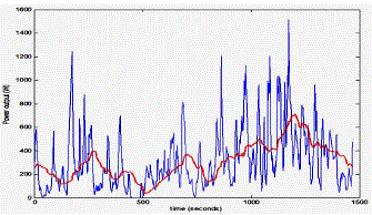
| Throughout a day, wind power varies continually withchange in wind speed. Wind turbine can deliver maximumpower when the rotor speed of PMSG varies according to the change in wind speed. Most recent papers try to extractmaximum power from wind turbine without using mechanicalsensors because of using these sensors lead to inaccuratemeasurements due to it includes mechanical parts. |
 |
 |
II. MODELLING OF A PMSM IN THE NATURAL ABC THREE-PHASE STATIONARY REFERENCE FRAME.
|
| Before developing the mathematical model of the PMSM, several important assumptions need to be made |
| (1) the damping effect in the magnets and in the rotor are negligible; |
| (2) the magnetic saturation effects are neglected; |
| (3) the eddy current and hysteresis losses are neglected; |
| (4) the back electromotive force (EMF) induced in the stator windings are sinusoidal; |
| (5) for simplicity, all the equations of PMSMs are expressed in motor (consumer/load) notation, that is, negative current will be prevailing when the model refers to a generator. Negative current means that at the positive polarity of the terminal of a device the current is out of that terminal. |
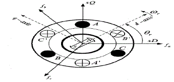
| Figure-5 shows the cross-sectional view of a three-phase, two-pole PMSM. The fixed abc axes denote the direction of the MMFs (fa,fb and fc) of the a, b and c phase windings, which are induced by the time varying three-phase AC currents in these stator phase windings. The flux caused by the permanent magnet is in the direction of the d-axis fixed at the rotor. Here, the dq-axes are rotating at the same angular speed of the PMs and rotor. Also, θrdenotes the angle between the d-axis and the stationary a-axis. |
| The state space relationship of the terminal voltages of the PMSM to the phase currents and the phase flux linkages due to the PMs and stator currents can be written as follows. |
 |
III.MODELLING OF THE PMSM IN THE DQ-AXES SYNCHRONOUSLY ROTATING REFERENCE FRAME
|
| The dq0 Park's transformation is a mathematical transformation which aims to simplify the analysis of synchronous machinery models, and was first introduced by R. H. Park in 1929. In the three-phase systems like PMSMs, the phase quantities which include stator voltages, stator currents, and flux linkages, are time varying quantities. By applying Park's transformation, which is in essence the projection of the phase quantities onto a rotating two axes reference frame, the AC quantities are transformed to DC quantities which are independent of time. The abc to dq0 transformation can be expressed in matrix form as follows: |
 |
| In expressions,Uabc and Udqocan represent the stator voltages, stator currents or flux linkages of the AC machines, respectively. Considering that under balanced conditions, U0=0, the voltage function of the PMSM in the dq-axes reference frame can be expressed as follows |
 |
VII.CONCLUSION
|
| • The whole system framework is illustrated, clarifies the aim of project and describes objects which will be achieved in this project. |
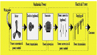
| • An overview of the fundamental principles relating to wind turbines with grid connection is presented. It briefly summarises what technologies are currently employed in the development of the converter wind turbine, and the achievement made by this project |
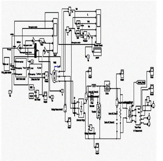
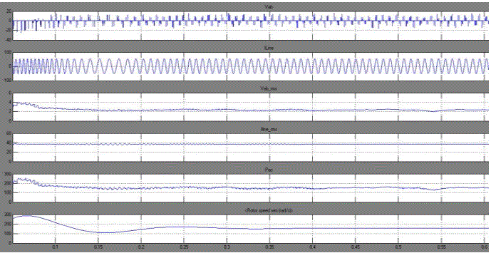
| • The non-dimension characteristic of the power coefficient of a wind turbine as function of the tip speed ratio is, successfully obtained. A MATLAB model for a PMSG system was created and simulated to meet the specifications of a 10kW wind turbine, and the outcomes demonstrate that the model meets the design parameters |
| • Demonstrates that the chosen diode rectifier with a boost circuit can be utilised for wind turbine generation with the generator voltage output less than that of the power grid. It means that this type of converter can be used in low wind speed conditions |
Figures at a glance
|
 |
 |
 |
 |
 |
| Figure 1 |
Figure 2 |
Figure 3 |
Figure 4 |
Figure 5 |
|
| |
References
|
- Bogdan S. Borowy and Ziyad M. Salameh, “Dynamic Response of a Stand-Alone Wind Energy Conversion System with Battery EnergyStorage to a Wind Gust”
- Akagi, H., Nabae, A., Atoh, S., "Control Strategy of Active Power Filter Using Multiple Voltage-Source PWM Converters", IEEE Transactions on Industry Applications, Vol. IA-22, No. 3, May/June 1986, pp. 460-465.
- Binns, K.J., Low, T.S., "Performance and application of multistacked imbricated Permanent-Magnet Generators", IEE Proc-B Electric Power Applications, vol 130, No 6, 1983, pp. 407-414.
- Ahmed T., Nishida K., &Nakaoka M. 2004, Wind Energy DC Supply-BasedInduction Generator with Static VAR Compensator and AC Voltage RegulatorIn INTELEC 2004, 26th Annual International, IEEE, pp. 689-696.
- Benesh, A.H., "The Benesh Wind Turbine", SED-Vol. 12, 11th ASME Wind Energy Symposium, ASME 1992, pp.153-154
|