Keywords
|
| Dynamic Modelling; Permanent magnet linear synchronous motor |
INTRODUCTION
|
| In today's competitive industrial environment, a tremendous amount of resources are dedicated to simple, optimal, and efficient solutions for the process automation, machine tool and material handling systems. Linear motors can give machine tools linear motion directly without indirect coupling mechanisms such as gear boxes, chains and screws. In particular, permanent magnet direct drive motors are becoming more and more popular in machine automation nowadays. The advantages of permanent magnet motor drives are their gearless structure, excellent control Characteristics like high speed, high acceleration and the most importantly, high motion precision and better efficiency. PMLSMs are used in lifts, paper machines, propulsion units of ships, windmills etc. |
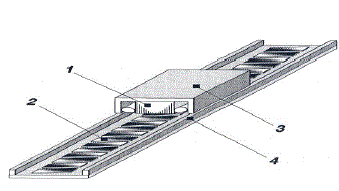
| In PMLSM, the moving part (mover) of which consists of a slotted armature and three-phase windings, while the surface permanent magnets (SPMs) are mounted along the whole length of the path (stator). |
| LSMs operating on the principle of the travelling magnetic field, the speed v of the moving part is equal to the synchronous speed ïÿýïÿýïÿýïÿý of the travelling magnetic field depends only on the input frequency f (angular input frequency ïÿýïÿý = 2ïÿýïÿýïÿýïÿý) and pole pitch ïÿýïÿý. It does not depend on the number of poles 2p. |
 |
| This paper is organized as follow: Section I gives the Introduction of the Permanent Magnet Linear Synchronous Motor. Section II is helpful to understand the analogy between permanent magnet linear synchronous motor and rotary motor . Section III explains the System dynamic modeling of motor. Section IV show the performance of open loop motor and Section V describes closed loop system and Section VI show the performance of closed loop motor the last section concludes the paper and followed by the references. |
ANALOGY BETWEEN THE PERMANENT MAGNET ROTARY SYNCHRONOUS MOTOR AND THE PMLSM
|
| The electrical model of the PMLSM can be obtained by analogy to a permanent magnet rotary synchronous motor, as shown in Fig. 2. For a rotary motor, the three armature windings shift one another by an electrical angle of 2π/3, and each winding covers an electrical angle of π in the stationary reference. |
| By analogy, the stator armature windings of a PMLSM shift one another by a distance of 2/3 (τ: pole pitch → step between two consecutive magnetic poles of secondary) and each winding covers a distance of the linear reference frame. |
| The electrical angle along which the primary of the PMLSM moves in the linear reference frame can be expressed by |
 |
| Here, Np is the electrical position constant of the PMLSM. |
| With the rapid development in computer hardware and software, new simulation packages which are faster and more user friendly are now available. This paper discusses the use of one such product, the SIMULINK software of MATLAB, in the dynamic modeling of the PMLSM. The main advantage of SIMULINK over other programming software is that, instead of compilation of program code, the simulation model is built up systematically by means of basic function blocks. Through a convenient graphical user interface (GUI), the function blocks can be created, linked and edited easily using menu commands, the keyboard and an appropriate pointing device (such as the mouse). A set of machine differential equations can thus be modeled by interconnection of appropriate function blocks, each of which performing a specific mathematical operation. Programming efforts are drastically reduced and the debugging of errors is easy. Since SIMULINK is a model operation programmer, the simulation model can be easily developed by addition of new sub-models to cater for various control functions. As a sub-model the PMLSM could be incorporated in a complete electric motor drive system. |
DYNAMIC MODEL OF PMLSM USING SIMULINK
|
| A generalized dynamic model of the PERMANENT MAGNET LINEAR SYNCHRONOUS MOTOR consists of an electrical sub-model to implement the three-phase to two-axis (3/2) transformation of stator voltage and current calculation, a thrust submodel to calculate the developed electromagnetic thrust, and a mechanical sub-model to yield the rotor or mover velocity. |
ELECTRICAL SUB-MODEL OF THE PMLSM
|
 |
THRUST SUB-MODEL OF PMLSM
|
 |
| Where flux = λpmïÿýïÿýïÿýïÿý |
MECHANICAL SUB-MODEL OF PMLSM
|
 |
| By taking laplace transform of above equation we obtain |
 |
 |
, |
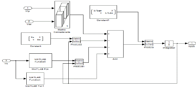
| The electrical sub-model in Fig-3, the thrust sub-model in Fig-4, the mechanical sub-model in Fig-5, are grouped together to form the PMLSM model as shown in Fig-6. |
OPEN LOOP RESULTS
|
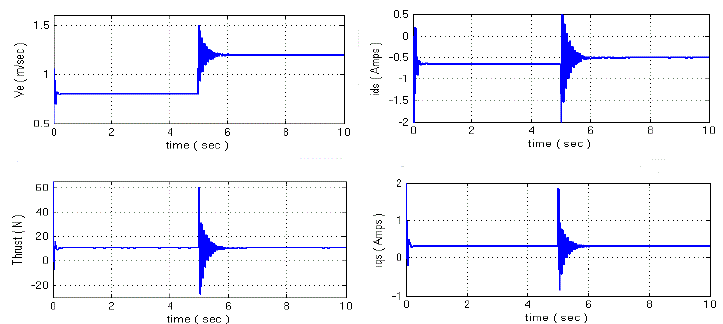
| Open loop simulation results for step change in speed at constant Load Thrust shown in fig-7 and for step change in Load Thrust at constant speed is shown in fig-8. |
CLOSED LOOP CONTROL SYSTEM
|
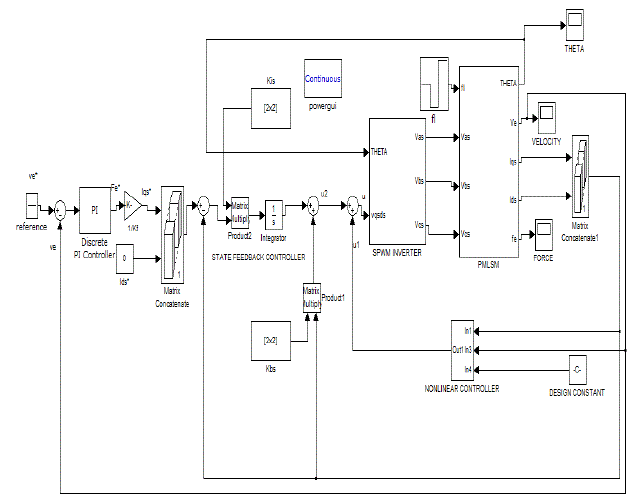
| In this paper, the proposed controller represented in the conventional two-loop structure for the motor drive is shown in Fig.9. The outer loop is the speed controller, the output of which is the reference value of the thrust Fe *. In field oriented control algorithm thrust is controlled by the q-axis current component. Hence the reference value of the currents iq * is computed from reference thrust while id* is zero. |
| The inner loop is the current controller which consists of a nonlinear controller by which the system nonlinearity is canceled using exact feedback linearization. The eigen values of the resulting linear systems are shifted by state feedback to appropriate locations in order to achieve the desire dynamic performance. Since the main task of the current controller is to follow reference thrust set by outer speed loop. For this purpose, the state feedback design is augmented with integral of output errors . |
CLOSED LOOP CONTROL RESULTS
|
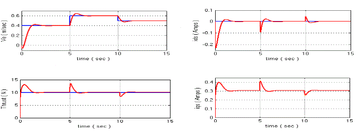
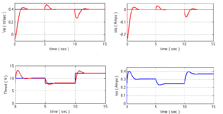
| Closed loop simulation results for step change in speed at constant thrust of 10N shown in Fig-10. Simulation results for step change in thrust at constant speed are shown in Fig-11. |
CONCLUSION
|
| In this paper we have used SIMULINK software of MATLAB to test the dynamic model of PMLSM at open loop & closed loop control. A generalized approach to the design of the speed control of Linear synchronous Motor has been presented by which the system nonlinearity is cancelled. In addition, a linear state feedback control law based on pole placement technique to achieve zero steady state error with respect to reference current specification is employed to improve the dynamic response. The closed loop control simulation shows good results. The predicted current step responses agreed well with the measurements and less overshoots were observed. |
SIMULATION PARAMETERS
|
| The permanent magnet linear synchronous motor chosen for the simulation studies has the following parameters: |
 |
 |
ACKNOWLEDGEMENT
|
| This work is supported by All India council of Technical Education(AICTE), New Delhi under Research Promotion Scheme, File no 8023/RID/RPS-78/2010-11 |
Tables at a glance
|
 |
| Table 1 |
|
| |
Figures at a glance
|
 |
 |
 |
 |
| Figure 1 |
Figure 2 |
Figure 3 |
Figure 4 |
 |
 |
 |
 |
| Figure 5 |
Figure 6 |
Figure 7 |
Figure 8 |
 |
 |
 |
| Figure 9 |
Figure 10 |
Figure 11 |
|
| |
References
|
- J. Yang,G. He, and J. Cui, “Analysis of PMLSM direct thrust control system based on sliding mode variable structure,” in Proc. IPEMC’06, pp. 1-5, 2006.
- Oskar Wallmark, “Modelling of Permanent-Magnet Synchronous Motors Machines with Non-Sinusoidal Flux Linkage”, Chalmers University of Technology, Sweden.
- Maloney, L. D., “Linear Motors Hit Their Stride”, Design News (Reed Business), 2005,
- W. Leonard, Control of Electrical Drives, Springer-Verlag, Berlin, 1996.
- Alice Mary, K., „Nonlinear Modeling, Control System Design and Implementation for an Inverter-fed Synchronous Motor Drive?, Ph.D. Thesis,Department of Electrical Engineering, I.I.T. Kharagpur, 1998.
- John Wiley & Sons, Parker, R.J., “Advances in Permanent Magnetism”, 1990.
- Jacek F. Gieras, Zbigniew J. Piech, BronislawTomcz “Linear Synchronous Motors: Transportation and Automation Systems (Electric Power Engineering Series)] “,2000 CRC press.
|