Keywords
|
| PV, MPPT, Grid synchronization, dq current control |
INTRODUCTION
|
| Distributed micro generation means generation of environmentally friendly electricity on small scale for individual customer use. Micro generation technologies include small scale wind turbines, micro hydro, photovoltaic systems etc. Among these, Photovoltaic generation system can be considered as the best solution for electricity production with rising fuel costs. Since the Photovoltaic generation system can be considered as the best solution for electricity production. It involves PV arrays, MPPT and Solar inverters. Grid connected PV generation system is having a relevance in this era. Evolution of PV system configurations involves centralised structure, the string structure, the multi string structure and the ac module structure [1] [2]. From the comparison of all these structures, new configuration has to be used to get reliable output. Modular configuration was introduced. In this paper, applying a new multilevel inverter topology to this system to improve the performance. Modelling of this system is done in MATLAB software. Comparison of new multilevel inverter with existing topology has been done in modelling. |
SYSTEM OVERVIEW
|
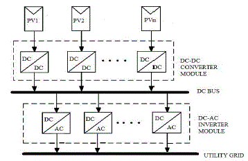
| A complete modular structure of the PV generation system consists of modular dc-dc converters and modular dc-ac inverters shown in fig.1. PV arrays are interfaced with their own dc-dc converter to a common dc bus, where the inverter modules are distributed and modularized instead of a centralized inverter. Voltage step-up and MPPT are obtained by the dc-dc converters. Both inputs and outputs of all the inverter modules are sharing the dc and ac bus without line transformer isolation. The inverter modules can inject a sinusoidal ac current into the utility grid with unity power factor with the regulated dc bus voltage when it is connected with grid. Each module unit in this generation system has independent functions. The structure of modular PV generation system is shown below. In this paper, modular PV configuration considered and application of single phase nine level inverter in this system analysed. To get a reliable and stable output from PV generation system, all these components have to be modelled and simulated by using MATLAB software. The next section explains the importance of grid tied inverter in this system. |
GRID TIED INVERTER
|
| Multilevel inverter improves the output wave form and it is suitable for grid connection. It reduces harmonic content in output. Therefore few of the multilevel inverters are analysed and single phase nine level inverter topology has chosen for the modular grid connected PV system [3]. Comparison table is given below. |
MODELLING OF GRID CONNECTED PV SYSTEM COMPONENTS
|
| PV MODULE: Solar cell is a large-area semiconductor diode; it is a basic element of this PV system. To increase the output power, photovoltaic cells are connected in series and parallel to form a module. The equivalent circuit of a PV cell is as shown in Figure 2. |
| The required equations for modelling PV array, the terminal equation for the current and voltage of the array is, |
 |
| BOOST CONVERTER: The DC/DC boost converter only needs four external components: Inductor, Electronic switch, Diode and output capacitor. P&O algorithm used here for the switching of converter. The value of inductance and capacitance can be found, |
 |
 |
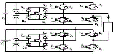
| SINGLE PHASE HYBRIDISED CASCADED NINE LEVEL INVERTER: It consists of two single phase five level PWM inverters are connected in series, giving nine voltage levels at the inverter output terminals [4]. And each of these five level PWM inverter consists of four switches, bidirectional switch connected to centre tap of two dc sources, four diodes. It results a total of ten switches shown in figure 3. |
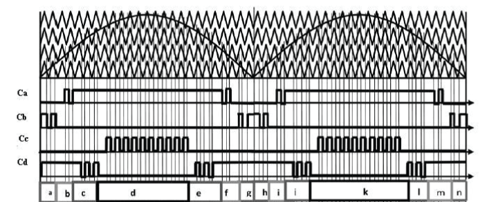
| The additional switches Sa and Sb must be properly switched considering the direction of the load current. Multicarrier phase disposition PWM scheme is used for the generation of the gating signals. It will generate gate signals by comparing the rectified sinusoidal modulating/reference signal, at the fundamental frequency, with four triangular carrier waves having higher switching frequency and in-phase. In this case, all the four carrier signals, T1-T4 have to be compared with the reference to produce switching signals for the power switches. It can be seen that six switches: S1, S4, S5, S8, SA and SB will be switching at the rate of the carrier signals frequency; whereas four switches: S2, S3, S6 and S7 will operate at the fundamental frequency. The gate signals are generated by the signals Ca-Cd coming from the comparators, which compare the respective triangular carrier signals with the reference wave. The gate signals g1-g8, gA and gB are produced by the logical combinations of the phase angle displacements and Ca- Cd. |
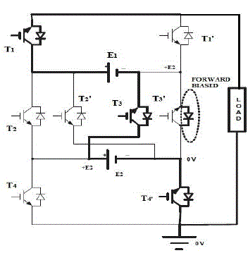
| SINGLE PHASE NINE LEVEL INVERTER: The single phase nine level inverter with two inputs DC sources for nine-level output is shown in Figure. The topology has eight switches and to obtain any desired voltage level, three switches need to be ON simultaneously as observed from Figure 4. Four pairs of complimentary switches are there. |
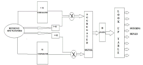
| In a multicarrier PWM scheme, comparing carrier signals with the reference signal and the pulses so obtained are used for switching of device corresponding to the respective voltage levels .In the proposed modulation scheme, for all the carrier waveforms above the time-axis, the results of comparison with the reference sine wave are 1 or 0. For all the carrier waves below the time-axis, the results of comparison with the reference sine wave are 0 or -1. The signals so obtained are aggregated so as to synthesize an aggregated signal As. The aggregated signal As has same number of levels as desired in the output waveform. The switching signals are derived from this aggregated signal by comparison of the signal with desired level and the output is fed to the switches corresponding to the level using the lookup table. |
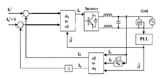
| GRID CONTROL - dq CURRENT CONTROL: When DC-AC inverter is connected with grid, voltage and phase should be synchronized with grid. Applying a switching pulse through PLL for inverter switching by adjusting sinusoidal reference voltage provided at inverter. The current control method based on a dq synchronous reference frame provides an infinite control loop gain at grid frequency and a superior disturbance rejection. In this case, the active power injected into the grid can be controlled transforming the current in the same reference frame and by acting on the amplitude of the Id component. The Iq component also be controlled in order to ensure zero reactive power injection. |
SIMULATION RESULTS AND ANLAYSIS
|
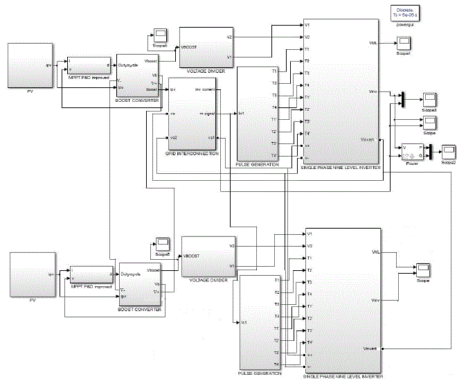
| Simulations have been performed in MATLAB/SIMULINK is shown below. |
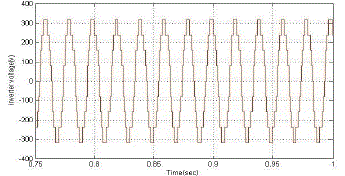
| Fig.7 having PV array, boost converter and single phase nine level inverter, utility grid interconnection. PV array modelling was done by considering 72 cells in series and it is having voltage output of 180v. Therefore voltage is boosted to a value of grid voltage by boost converter. Single phase nine level multilevel inverter is used here and it is having two dc voltage source inputs. And it consists of 8 switches. It uses multi carrier PWM method for switching. This inverter with load gives 325 v nine level output with some distortions. RL load is connected at inverter side and through a filter it is synchronized with grid. By taking inverter load current and grid current as Iα and Iβ giving to the dq current control block for active power improvement. |
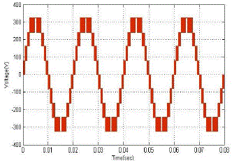
| In figure 7, introducing an existing topology single phase hybridised nine level inverter and observed the results, which shown in the figure 8(a) and (b). THD value is obtained as 13.90% for existing topology. More interharmonics are there and it will make the system less efficient. And a good nine level output waveform is obtained here with magnitude 325 v and THD 11.40 shown in figure 9(a) and (b)(one module section). Interharmonics are less for single phase nine level inverter. And THD value obtained is 11.40%. |
CONCLUSIONS
|
| In this modular structure, the system is simulated with single phase nine level inverter and existing multilevel inverter topology. The benefits of new multilevel inverter and inferences from this simulation. |
| 1. Device count reduced and hence total system cost reduced. |
| 2. Malfunctioning of any module section will not affect the entire system due to its modular structure |
| 3. THD content reduced to low value. |
| More than nine levels can also be used in this system, but it will make the system more bulkier. Here this topology with nine level keeps the THD value below the safe range and at the same time makes the system more efficient. New multilevel structure is having low THD content than existing topology. Multi carrier PWM method is very simple and there is no complex logical sequences like in PWM method used in single phase nine level cascade inverter. |
Tables at a glance
|
 |
| Table 1 |
|
| |
Figures at a glance
|
 |
 |
 |
 |
 |
| Figure 1 |
Figure 2 |
Figure 3 |
Figure 4 |
Figure 4b |
 |
 |
 |
 |
 |
| Figure 5 |
Figure 6 |
Figure 7 |
Figure 8a |
Figure 9a |
|
| |
References
|
- Li Zhang,Kai Sun, Xing, LanlanFeng, and HongjuanGe,``A Modular Grid-Connected Photovoltaic Generation System Based on DC Bus",IEEE Transactions On Power Electronics, Vol.26, No.2, February 2011.
- T. Kerekes, R. Teodorescu, M. Liserre, C. Klumpner, and M. Sumner,`` Evaluation of three-phase transformerless photovoltaic invertertopologies”, IEEE Trans. Power Electronics., vol. 24, no. 9, pp. 2202-2211, Sep.2009.
- SurinKhomfoi and Leon M. Tolbert, Chapter 31 Multilevel Power Converters, 2008
- Charles I. Odeh, Damian B.N. Nnadi, ``Single-phase 9-level hybridised cascaded multilevel inverter,"IET Power Electronics, Vol. 6, Iss. 3,pp.468-477, 2013.
- Krishna Kumar Gupta, Shailendra Jain ,``A multilevel Voltage Source Inverter (VSI) to maximize the number of levels in output waveform”,Electrical Power and Energy Systems 44 (2013) 2536
- N. Pandiarajan and Ranganath ,``Mathematical Modeling of Photovoltaic Module with Simulink”, International Conference on Electrical EnergySystems (ICEES 2011), 3-5 Jan 2011
- Sk. Md. GolamMostafa,``Designing a Boost Inverter to Interface between Photovoltaic System and Power Utilities”, IOSR Journal of Electricaland Electronics Engineering (IOSR-JEEE) ISSN: 2278-1676 Volume 3, Issue 2, PP 01-06 , (Nov. - Dec. 2012)
- Miranda U.A;Rolim L.G.B and Aredes M,``A dq synchronous reference frame current control for single phase converters”,in Proc. Of PowerElectronics Specialists Conference, pp.1377-1381, 2005.
|