Keywords
|
| Multilevel Inverter,MPPT, Cascade H-Bridge, Newton Rapson and PIcontroller. |
INTRODUCTION
|
| In recent years, with the development of PV power plant system, MPPT, and multilevel inverter technologies, higher requirement in voltage level, flexibility and reliability [1]. The solar panel can be used as a component of a larger PV system to generate and supply electricity in commercial and residential applications,as the result peak power of the load and the reliability of power output can be improved. More stable power supply performance can be achieved by using multilevel inverter control strategy including voltage stability and the proposed topology significantly reduces the number of switches, IGBTs, and power diodes as the number of output voltage levels increases [2] a single phase five level inverter for grid connected photovoltaic system with pi controller is mentioned in [3]by using the a five level symmetrically defined selective harmonic elimination PWM Strategy harmonic content has been reduced with the help of better harmonic spectra [4].[5] .Improved Phase Disposition Pulse Width Modulation (PDPWM) for Modular Multilevel Inverter is used for PV grid-connection with new modulation method which is based on Selective Virtual Loop Mapping (SVLM) and to achieve dynamic capacitor voltage balance without the help of an extra compensation signal[6].An optimal solution for eliminating pre specified order of harmonics from a stepped waveform of a multilevel inverter topology with equal dc sources[7]. A new approach for modulation of a 7-level cascade multilevel inverter using selective harmonic elimination is presented. The dc sources feeding the multilevel inverter are considered to be varying in time, and the switching angles are adapted to the dc source variation. This method uses genetic algorithms to obtain switching angles offline for different dc source values[8].There are many limitations in extracting power from renewable energy resources. To minimize the power demand and scarcity we have to improve the power extracting methods. Multilevel inverter is used to extract power from solar cells. It synthesizes the desired ac output waveform from several dc sources. It focuses on improving the efficiency of the multilevel inverter and quality of output voltage waveform[9]. The simplest way of implementing an Maximum Power Point Tracking is to operate a Photovoltaic array under constant voltage and power reference to modify the duty cycle of the dc-dc converter. This will keep operation constant at or around the maximum peak power point. classification of the MPPT techniques have made based on features, such as number of control variables involved, types of control strategies employed, types of circuitry used suitably for PV system and practical/ commercial applications is mentioned in [10].[11]Cascade H-Bridge multilevel inverter, switching angles at fundamental frequency are obtained by solving the selective harmonic elimination equations in such a way that the fundamental voltage is obtained as desired and certain lower order harmonics are eliminated. A new approach is presented to implement the Newton-Rapson method for solving the transcendental equations which produces all possible solutions with any random initial guess and for any number of levels of multilevel inverter.To solve the nonlinear transcendental equations system by using the harmonic elimination technique with Pulse Width Modulation (PWM) is more in depth method and also studied in the field of MMC.A new implementation scheme based on real-time solving of the nonlinear harmonic elimination equations using feed forward Artificial Neural Networks (ANNs) is reported in [12] |
| This paper is proposed to design an improved 9-level cascaded H-Bridge multilevel inverter applications using standalone photovoltaic techniques.PI controller with Sinusoidal pulse width modulation (sin PWM) sinusoidal steeped output waveform is obtained and the harmonics are reduced .The Newton Rapson algorithm and PI controller are used for Modular Multilevel PV Inverter .It is also used to drive an Induction motor from the inverter output. |
PHOTOVOLTAIC SYSTEM
|
| Energy from our sun is one such example. Technically, the sunlight will fade in about 5 billion years, but for all practical purposes and human timescales, this is a continuous and infinite resource. Solar Panels use arrays of solar PV cells to convert photons into usable electricity.Installing solar panels with a synchronous or multifunctional solar inverter allows us to use city electricity in emergency times. Photovoltaic Operation is the direct conversion of light into electricity at the atomic level. Some materials exhibit a property known as the photoelectric effect that causes them to absorb photons of light and release electrons. When these free electrons are captured, electric current results that can be used as electricity. For solar cells, a thin semiconductor wafer is specially treated to form an electric field, positive on one side and negative on the other. When light energy strikes the solar cell, it produces an electric power which can be fed to the desired load. |
A. Equivalent Circuit of a PV Cell
|
| The most commonly known solar cell is configured as a large-area p-n junction made from silicon. The schematic representation of a typical Solar cell is shown in the Figure 1 |
| An ideal solar cell may be modeled by a current source in parallel with a diode; in practice no solar cell is ideal, so a shunt resistance and a series resistance component are added to the model. The resulting equivalent circuit of a Solar Cell is shown in the Figure 2 |
MAXIMUM POWER POINT TRACKING
|
| MPPT algorithms are necessary in PV applications because the MPP of a solar panel varies with the irradiation and temperature, so the use of MPPT algorithms is required in order to obtain the maximum power from a solar array. These techniques differ in many aspects such as required sensors, complexity, cost, range of effectiveness, convergence speed, correct tracking when irradiation and/or temperature change, hardware needed for the implementation or popularity, among others. A complete review of 19 different MPPT algorithms can be found in among these techniques, the P&O and the Incremental Conductance algorithms are the most common. However, if the PV array is partially shaded, there are multiple maxima in these curves. |
| The P&O algorithm is also called “hill-climbing”, but both names refer to the same algorithm depending on how it is implemented. Hill-climbing involves a perturbation on the duty cycle of the power converter and P&O a perturbation in the operating voltage of the DC link between the PV array and the power converter In the case of the Hill-climbing, perturbing the duty cycle of the power converter implies modifying the voltage of the DC link between the PV array and the power converter, so both names refer to the same technique. |
| In this method, the sign of the last perturbation and the sign of the last increment in the power are used to decide what the next perturbation should be on the left of the MPP incrementing the voltage increases the power whereas on the right decrementing the voltage increases the power. If there is an increment in the power, the perturbation should be kept in the same direction and if the power decreases, then the next perturbation should be in the opposite direction. Based on these facts, the algorithm is implemented.The process is repeated until the MPP is reached Finally MPPT methods do not offer any improvement to the original P&O algorithms. |
MULTILEVEL INVERTER
|
A. Basic Concepts Of Multilevel Inverter.
|
| Industry has begun to demand higher power equipment, which now reaches the megawatt level. Controlled AC drives in the megawatt range are usually connected to the medium voltage network. Multilevel inverters include an array of power semiconductors and capacitor voltage sources, the output of which generate voltages with stepped waveforms. The commutation of the switches permits the addition of the capacitor voltages, which reach high voltage at the output, while the power semiconductors must withstand only reduced voltagesA semiconductor is represented by an ideal switch with several positions. A two level inverter generates an output voltage with two values (levels) with respect to the negative terminal of the capacitor (Figure 4.a), while the three level inverter generates three voltages and so on.Considering that is the number of steps of the phase voltage with respect to the negative terminal of the inverter, then the number of steps in the voltage between two phases of the load is k=2m+1 and the number of steps in the phase voltage of a three phase load in wye connection is p=2k-1. By increasing the number of levels in the inverter, the output voltages have more steps generating a staircase waveform (Figure.4C) which has a reduced harmonic distortion. Three different topologies have been proposed for multilevel inverters: diode clamped (neutral point clamped); capacitor clamped (flying capacitors); and cascaded multi cell with separate dc sources. In addition, several modulation and control strategies have been developed or adopted for multilevel inverters including the following: multilevel sinusoidal pulse width modulation (PWM), multilevel selective harmonic elimination, and space vector modulation (SVM). |
B. Proposed Cascaded H-Bridge Multilevel Inverter
|
| A single-phase structure of an m-level cascaded inverter is illustrated in Figure6 Each separate dc source (SDCS) is connected to a single-phase full-bridge, or H-bridge, inverter. Cascaded H-bridge multilevel inverters typically use IGBT switches.These switches have low block voltage and high switching frequency. In this topology the number of phase voltage levels at the converter terminals is 2N+1, where N is the number of cells or dc link voltages. |
| In this topology, each cell has separate dc link capacitor and the voltage across the capacitor might differ among the cells. So, each power circuit needs just one dc voltage source. The number of dc link capacitors is proportional to the number of phase voltage levels .Each H-bridge cell may have positive, negative or zero voltage.Final output voltage is the sum of all H-bridge cell voltages and is symmetric with respect to neutral point, so the number of voltage levels is odd. |
C. Operation of Cascade H-Bridge Multilevel Inverter
|
| Each inverter level can generate three different voltage outputs, +Vdc , 0, and –Vdc by connecting the dc source to the ac output by different combinations of the four switches, S1 , S2 , S3 , and S4 .To obtain +Vdc, switches S1 and S4 are turned on, whereas –Vdc can be obtained by turning on switches S2 and S3 . By turning on S1 , S2 , S3 , and S4 , the output voltage is 0. The ac outputs of each of the different full-bridge inverter levels are connected in series such that the synthesized voltage waveform is the sum of the inverter outputs. The number of output phase voltage levels m in a cascade inverter is defined m = 2s+1,where s is the number of separate dc sources. |
| In the 9-level H-bridge cascaded multilevel inverter with separate DC sources are being studied.This method uses newton rhapson algorithms to obtain switching angles offline for different DC source values and uses neural networks to determine the switching angles that correspond to the real-time values of the DC sources for each phase. The ac outputs of each of the different full-bridge inverter levels are connected in series such that the synthesized voltage waveform is the sum of the inverter outputs.This implies that each one of the DC sources of this topology can have different values at any time but the output fundamental voltage will stay constant and the harmonic content will still meet the specifications. The switching angles are updated at each cycle of the output fundamental voltage. More detail on harmonic elimination techniques will be presented in the next section. Three has demonstrated a prototype multilevel cascaded static var generator connected in parallel with the electrical system that could supply or draw reactive current from an electrical system. Cascaded inverters are ideal for connecting renewable energy sources.The advantage of Cascade H-Bridge Multilevel Inverter is the number of possible output voltage level is more than twice the number of DC sources. The series of H-bridge makes for layout and packaging. This will enable the manufacturing process to be done more quickly and cheaply. |
D. Newton-Rapson Method
|
| The Newton-Rapson (N-R) method is one of the fastest iterative methods. This method begins with an initial approximation. In the 9-level H-bridge cascaded multilevel inverter with separate DC sources are being studied. The DC sources feeding the multilevel inverter are considered to be varying in time. The switching angles are updated at each cycle of the output fundamental voltage.The conducting angles 1.2.3..s can be chosen such that the voltage total harmonic distortion is a minimum. Generally, these angles are chosen so that predominant lower frequency harmonics, 5th, 7th, 11th, and 13th harmonics are eliminated. More detail on harmonic elimination techniques will be presented in the next section. Cascaded inverters are ideal for connecting renewable energy sources.The advantage of Cascade H-Bridge Multilevel Inverter are The number of possible output voltage level is more than twice the number of DC sources. The series of H-bridge makes for layout and packaging. This will enable the manufacturing process to be done more quickly and cheaply |
MODULATION TECHNIQUES
|
| The multilevel topology involves several modulation techniques. Each technique involves different modulation methods. The well-known modulation topologies for multi-level inverters as follows: |
| ïÃâ÷ Sinusoidal or “Sub harmonic” Natural Pulse Width Modulation (SPWM). |
| ïÃâ÷ Selective Harmonic Eliminated Pulse Width Modulation (SHE PWM) or Programmed-Waveform Pulse Width Modulation (PWPWM) |
| ïÃâ÷ Optimized Harmonic Stepped-Waveform Technique (OHSW) |
A. Pulse Width Modulation Technique
|
| The most efficient method of controlling the output voltage is to incorporate PWM control within the inverters. In this method, a fixed DC input voltage is supplied to the inverter and a controlled AC output voltage is obtained by adjusting the on and–off periods of the inverter devices. Voltage-type PWM inverters have been applied widely to such fields as power supplies and motor drivers. This is because: (1) such inverters are well adapted to high-speed self-turn-off switching devices that, as solid-state power converters, are provided with recently developed advanced circuits (2) they are operated stably and can be controlled well. |
| The commonly used PWM control techniques are: |
| (a) Sinusoidal pulse width modulation (sin PWM) |
| (b) Space vector PWM |
| The performance of each of these control methods is usually judged based on the following parameters: a) Total harmonic distortion (THD) of the voltage and current at the output of the inverter, b) Switching losses within the inverter, c) Peak-to-peak ripple in the load current, d) Maximum inverter output voltage for a given DC rail voltage.From the above all mentioned PWM control methods, the Sinusoidal pulse width modulation is applied in the proposed inverter since it has various advantages over other techniques. Sinusoidal PWM inverters provide an easy way to control amplitude, frequency and harmonics contents of the output voltage. |
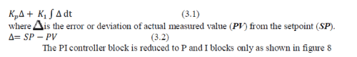
PI CONTROLLER
|
| In control theory, a controller is a device, possibly in the form of a chip, analogue electronics, or computer, which monitors and physically alters the operating conditions of a given dynamical system.In control engineering, a controlled system is primarily characterized by its dynamic behaviour which also determines the scope and quality required to solve a control task This is determined by measuring the controlled variable after a step change in the manipulated variable. |
 |
SIMULATION RESULTS
|
A. Proposed Overall Simulation Diagram
|
| The simulation model is shown in figure 11, The nine level cascade H-bridge multilevel inverter powered by PV system has been developed by using MAT LAB with the use of this proposed method sinusoidal steeped output waveform is obtained and the harmonics are reduced. The inverter must perform reliably and efficiently to supply a wide range of ac loads with the voltage and required power quality necessary for reliable and efficient load and system performance. The multilevel inverter is designed to allow interconnection MPPT with PV system. |
| In the 9-level cascaded multilevel inverter with separate DC sources are being studied. The DC sources feeding the multilevel inverter are considered to be varying in time. This method uses Newton Rapson algorithms to obtain switching angles offline for different DC source values and uses neural networks to determine the switching angles that correspond to the real-time values of the DC sources for each phase. and the harmonic content will still meet the specifications. |
B. Simulation Model of PI Controller
|
| The simulation diagram of the PI controller is shown in the Figure 12 The proportional –Integral controller is output signal every sample time(T), to the control element. PI controllers have two tuning parameters to adjust. While this makes them more challenging to tune than a P-only controller they are not as complex as the two parameters PI controller hence is used for pulse width modulation technique. |
C. Simulation Model of 9-Level Cascaded H-Bridge Multilevel Inverter
|
| The nine- level multilevel inverter has been developed by using MATLAB. To operate cascaded multilevel inverter using a solar source. |
| Considering a cascaded multilevel inverter with four H-bridges and the eleven level stepped output voltage is obtained. Simulation model of nine level cascade multilevel inverter modulation scheme are pulse width modulation technique is obtained. It consists of PWM generator block has parameters such as amplitude, pulse width period and phase delay which are used to determine the shape of the output |
D. Output Voltage Waveform Of A Pv Panel
|
| The output of the PV is shown in Figure 14. The PV output of 21.8 V is obtained by adjusting the values of temperature. The amount of power produced by the PV system depend on the amount of PV radiation . |
E. Output Voltage Waveform OfMppt Dc/Dc Converter
|
| The output of the MPPT DC/DC converter is shown in Figure 16 MPPT is used for solar installation system. The output voltage varies with the input voltage. And this MPPT good output regulation. |
F. Output Waveform Of Cascaded H-Bridge Multilevel Inverter
|
| The output of cascade H-bridge nine level multilevel inverter is shown in Figure 17 and 18 the output voltage and output current has nine levels. It can be achieved by using selection switching pattern method. In Figure shown below waveform is obtained is voltage and current Vs time. The output nine level multilevel inverter fundamental frequencies is 50 HZ. |
| The loads connected across the cascaded H-bridge multilevel inverter. Due to the parallel connection, voltage remains constant for all the resistive loads. But current varies as per the connected load, |
| In the Figure 17 the output current of cascaded H-bridge multilevel inverter is (2.3 Amp) for resistive load (RL1=10000Ω) at constant 230 voltage |
CONCLUSION
|
| This article first discussed the possibilities of MMC being used as an interface between the single phase induction motor and PV panels, and proposed an improved multilevel inverter based on the sinusoidal PWM. This method can produce nine level output in MMC Simulation results were carried out under the conditions of load and the effectiveness of the method was proved well. |
Figures at a glance
|
 |
 |
 |
 |
 |
| Figure 1 |
Figure 2 |
Figure 3 |
Figure 5 |
Figure 6 |
 |
 |
 |
 |
 |
| Figure 8 |
Figure 11 |
Figure 12 |
Figure 13 |
Figure 14 |
 |
 |
 |
| Figure 15 |
Figure 16 |
Figure 17 |
|
References
|
- YaosuoXue, Kurthakoti C. Divya, GerdGriepentrog, et al., “Towards Next Generation Photovoltaic Inverters,” IEEE Energy ConversionCongress and Exposition (ECCE), 2011, pp. 2467 - 2474.
- JavadEbrahimi and EbrahimBabaei“A New Multilevelconverter Topology With Reduced Number of PowerElectronicComponents”IEEEFEBRUARY 2012.
- R. Anand and A.Nazar Ali “A Single phase Five level Inverter for Grid Connected Photovoltaic System by employing PID Controller”AfricanJournalOf Scientific Research 2011.
- Agelidis, V. G.Balouktsis, A. I.Dahidah, M. S.A. “ A Five Level Symmetrically Defined Selective Harmonic Elimination PWM Strategy”IEEEJan 2008
- Jun Me, Bailu Xiao, KeShen, “Modular Multilevel Inverterwith New Modulation Method and Its Application to Photovoltaic Grid-ConnectedGenerator”IEEE,jan 2013
- MaruthuPandiPerumal —DevarajanNanjudapan“Performance Enhancement Of Embedded System Based Multilevel Inverter Using GeneticAlgorithm” Ieee Nov 2012.
- FaeteFilho,HelderZandonadi Maia, Tiago H. A. Mateus,andBurakOzpineci“Adaptive Selective Harmonic Minimization Based on annsforCascade Multilevel Inverters With Varying DC Sources”, IEEE may 2013.
- Gobinath.K1, Mahendran.S2, and Gnanambal.I3“New cascaded H-bridge Multilevel Inverter with Improved Efficiency” International Journal ofAdvanced Research in Electrical, Electronics and Instrumentation Engineering, April 2013
- Oscar López-Lapeña and Maria Teresa Penella“A New MPPT Method for Low Power Solar Energy Harvesting” In IEEE trans. Industrialelectronics, vol. 57, no. 9, September 2010.
- BidyadharSubudhi and RaseswariPradhan“A Comparative Study on Maximum Power Point Tracking Techniques for Photovoltaic PowerSystems”.IEEE2013.
- Jagdish Kumar, Biswarup Das, and PramodAgarwal, “Selective Harmonic Elimination Technique for a Multilevel Inverter” IEEE December2008
- O. Bouhali, F Bouaziz, N. Rizoug and A. Talh”Solving Harmonic Elimination Equations in Multi-level Inverters by using Neural Networks“IEEE March 2013
|