Keywords
|
| Bridge type design, Figure of merit, Micro thermoelectric generator, Solar energy conversion. |
INTRODUCTION
|
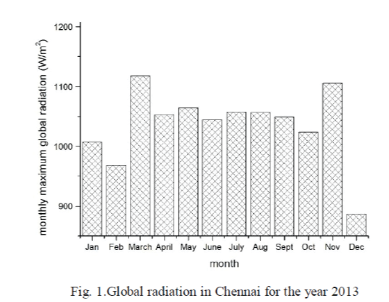
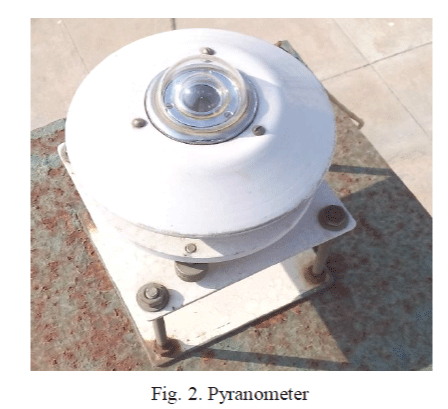
| In recent years, the production of electricity has become lesser than the needs. This has led to the research on innovative technologies for the production. On the other hand, energy from the solar radiation is getting wasted as heat energy. Figure 1 shows the monthly maximum global radiation in Chennai for the year 2013 which was obtained using pyranometer (Fig. 2). Thus the solar heat is utilized for the generation of electrical power.The existing generators are not optimal in design and material used. The proposed system aims at developing a micro thermoelectric generator with optimum thermo leg length and optimum design operating at maximum capacity for solar energy conversion. |
| Various miniaturized thermoelectric generators are developed [1-4]. In [1], NiCu based μ TEG that can generate a power of up to 2.6*10-3 μWcm-2K-2 and Bi2Te3 based μ TEG that can generate a power of 0.29 μWcm-2K-2 are developed. In [2], a μ TEG that has an output voltage of 670μV for the temperature difference of 10K is developed. Various μ TEGs for solar energy conversion are also developed [3], [4]. In [3], a transparent bridge typeμ TEG is developed which can be integrated with the windows of the building, so that the temperature difference between inside and outside are utilized for the generation of electrical power. This design produces a power of 1.0W for the temperature difference of 10K.In [4], a μ TEG which can generate a power of 8W from 75cm * 75cm area for lighting LED is developed. |
PROPOSED SYSTEM
|
| A. Material |
| The material that has high thermoelectric energy transformation capacity can be determined by the term figure of merit, Z with |
 |
| where α is the seebeck coefficient, ρ the resistivity, λ the thermal conductivity of the material. Equation (1) shows that the materials having high seebeck coefficient, low resistivity and low thermal conductivity are considered asthermoelectric materials. But while choosing the apt material, technological aspects also have to be considered. The silicon because of its well established technology and high seebeck coefficient as shown in Table I, it can be chosen as a thermoelectric material though it has high thermal conductance. The Table I gives the seebeck coefficient of different thermoelectric materials. |
| B. Material parameters |
| Reference [3] shows that the maximum of thermoelectric energy conversion (maximum figure of merit, Zmax) for mono crystalline silicon lies at a resistivity of 4*10-5 Ω m which can be achieved by appropriate doping concentration. Table II shows the optimum thermoelectric properties of silicon at room temperature. |
| C. Design |
| The existing designs can be grouped into three depending upon the setup and the heat flow. |
| Type1-Generators with lateral heat flow and laterally fabricated thermocouples [5]. This is due to the limitations in the thickness of the thin film deposition techniques. |
| Type2-Generators with vertical heat flow and laterally fabricated thermocouples [6]. |
| Type3-Generators with vertical heat flow and vertically fabricated thermocouples [3], [9]. Recently developed fabrication technology allow for the vertical fabrication. |
| The thermal contact of the generators with the heat source and sink increases from type1 to type3. |
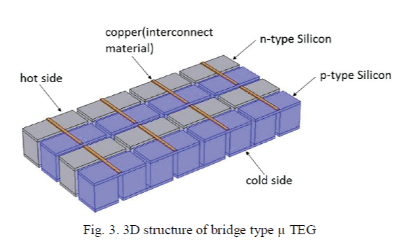
| The proposed design as shown in Fig. 3 is of type3 which includes p and n type silicon as thermocouple elements arranged in a bridge like fashion connected electrically in series and thermally in parallel and interconnected to each other by a bridge of conductor (Cu). This bridge type design has less contact resistance and it is highly reliable. For analysis, thickness of the interconnect material isassumed as 2μm, gap between the thermo legs as 10μm, area of the thermo legs as 50μm * 50μm, hot side temperature(Th) as 310K and cold side temperature(Tc) is varied from 300K to 308K. |
OPTIMIZATION OF THERMO LEG LENGTH
|
| One of the main requirements on improving the output power of the thermoelectric generator is the optimum module geometry in which the thermo leg length plays an important role. The length must be optimized such that it meets the requirements for maximum power output and maximum conversion efficiency. In cases where the input thermal energy is free, the thermo leg length should be optimized such that the power output is maximum neglecting the conversion efficiency. |
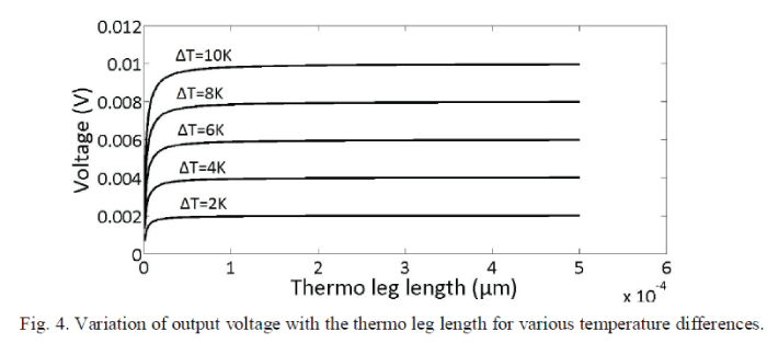
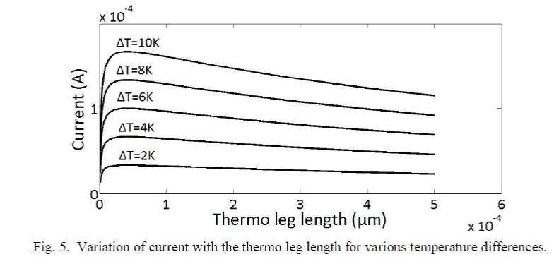
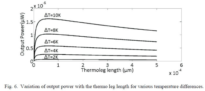
| The following results (Fig. 4, Fig. 5, and Fig. 6) are obtained for a single thermocouple with optimum material parameters for various temperature differences (ΔT) based upon an improved theoretical model which takes into account the thermal and electrical contact resistances [10].Figure 4 shows that at the temperature difference of 10K, as the thermo leg length increases from 1μm to 500 μm, the output voltage (V) increases from 3.3mV to 10mV. Figure 5 shows that at the temperature difference of 10K, as the thermo leg length increases from 1μm to 45μm, the current(I) increases from 60.6mA to 167.1mA and then decreases beyond 45μm.Figure 6 shows that at the temperature difference of 10K, as the thermo leg length increases from 1μm to 59 μm, the output power increases from 0.2μW to 1.6065μW and then decreases beyond 59 μm.Thus the power output (P=V*I) has been increased from 1.5μW [5] to 1.6065 μW for a silicon based single thermocouple when doped with optimum carrier concentration and when its thermo leg length is optimum, for the temperature difference of 10K. |
DESIGN AND SIMULATION IN COMSOL
|
| To design and simulate thermoelectric generator in COMSOL, “Thermoelectric Effect” physics is added to the physics of COMSOL. The thermoelectric equations as given in [4] are included in the “Thermoelectric Effect” physics of COMSOL Multiphysics. |
| A. Single thermocouple |
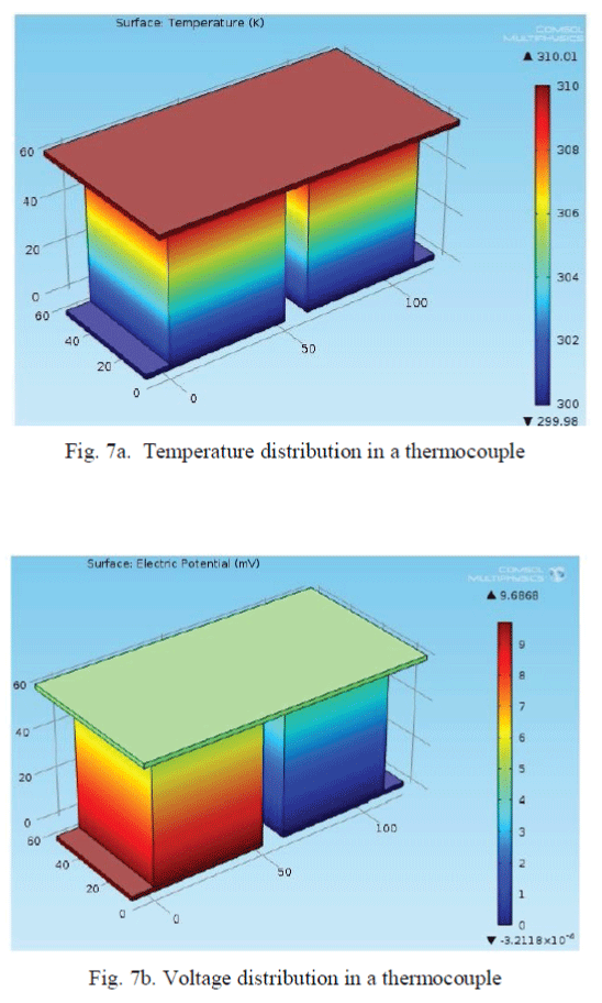
| The temperature distribution and the voltage distribution in a single thermocouple for the temperature difference of 10K is shown in Fig. 7a and Fig. 7b respectively.The simulation results show that 9.6868mV is obtained for the optimum leg length of 59 μm. |
| B. Bridge type design |
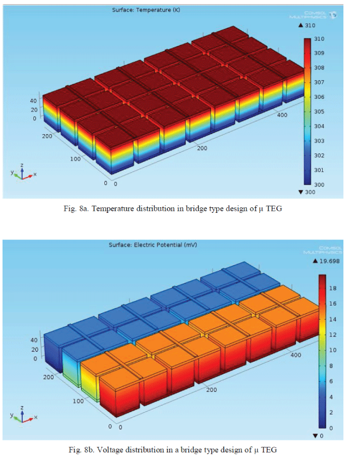
| Figure 8a and Figure8b shows the temperature distribution and voltage distribution respectively for the bridge type design consisting of 2 thermocouples in series and 8 parallel paths. Such design generates an output voltage of 19.698mV for the temperature difference of 10K. |
CONCLUSION
|
| The developed micro thermoelectric generator can be used as an electric source for many applications. One such application is glowingLED that can illuminate a room.Since the developed optimum thermocouple generates output voltage of 9.6868mV and output power of 1.6065μW, the area required to glow 10W, 12V LED has beed reduced from 75cm × 75cm [4] to 15cm * 30cm. |
Tables at a glance
|
 |
 |
| Table 1 |
Table 2 |
|
Figures at a glance
|
 |
 |
 |
 |
| Figure 1 |
Figure 2 |
Figure 3 |
Figure 4 |
 |
 |
 |
 |
| Figure 5 |
Figure 6 |
Figure 7 |
Figure 8 |
|
References
|
- Wulf Glatz, Etienne Schwyter, Lukas Durrer and Christofer Hierold, “Bi2Te3-Based Flexible Micro Thermoelectric Generator With Optimized Design,” Journal of Microelectromechanical Systems, vol. 18, no.3, pp. 763-772, June 2009.
- Pin-Hsu Kao. Po-Jen Shih, Ching-Liang Dai, “Fabrication and Characterisation of CMOS-MEMS Thermoelectric Micro Generators,”Journal of sensors, vol. 10, no.2,pp. 1315-1325, 2010.
- Guan-Ming Chen, I-Yu Huang, et al., “Development of a Novel Transparent Micro-Thermoelectric Generator for Solar Energy Conversion,” in Proc. 6th IEEE International Conference on Nano/Micro Engineered and Molecular Systems, pp. 976-979, Feb. 2011.
- Y. Jeyashree, Pheba Cherian, A. Vimala Juliet, “Micro Thermoelectric Generator-A source of Clean Energy,” International Conference on Microelectronics, Communication and Renewable Energy (ICMiCR-2013), pp. 1-5, June 2013.
- H. Glosch, M. Ashauer, U. Pfeiffer and W. Lang, “A thermoelectric converter for energy supply [using silicon micromechanics],” Sens. Actuators A, Phys., vol. 20, pp.1-3, 1999.
- M. Strasser et al., “Micromachined CMOS thermoelectric generators as on chip power supply,” Sens. Actuators A, Phys., vol.114, no. 2/3, pp.362-370, Sep. 2004.
- K. Itoigawa et al., “Fabrication of flexible thermopile generator,” J.Micromech. Microengg. , vol.15, no. 9, pp. S233-S238, Sep. 2005.
- H. Bottner et al., “New thermoelectric components using microsystem technologies,” Journal of Microelectromechanical System, vol. 13, no. 3,pp. 414-420, Jun. 2004.
- M.Kishi et al., “Micro thermoelectric modules and their application to wrist watches as an energy source,” in Proc. 18th ICT, 1999, pp. 301-307.
- Min, G., and Rowe, D.M.: “Optimisation of thermoelectric module geometry for waste heat electrical power generation,” J. Power Source, 38, pp. 253-259, 1991.
|