Keywords
|
| GSM band, ISM band, Fractal, PIFA structure and CST Microwave studio |
INTRODUCTION
|
| Constrains on wireless antenna design include requirement for multi-band resonance. Dual band, tri band, quad band, and dual mode cellular phone is an example of a multiple frequency wireless devices. Dual band operation involves transmitting and receiving in both 850 MHz and 1900 MHz frequencies in GSM mode where as dual mode involves operating in both CDMA and GSM modes. Traditional antennas are unable to meet these requirements and hence alternative approaches are needed. Reconfigurable antennae using it multiband antennae can be obtained. Generally reconfigurability can be obtained using following techniques: Tunable elements in feeding networks, adaptive matching networks, phase shifters and tunable filters, tunable elements embedded such as PIN diode, MEMS and optimal switching in the radiating elements. But it is bulky and we get one band at a time. So recent antenna developments have applied fractal mathematics to antenna design, resulting in new fractal antennas with multi-band behavior. |
FRACTAL CONCEPT
|
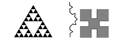
| Fractal antennas are reliable and cost-effective. Fractal antennas allow for multiband capabilities, decreased size, and optimum smart antenna technology. Fractals have self similar shapes and space filling properties that can be subdivided into parts. This property makes the fractal antenna compact and operating in wideband frequencies. The different fractal elements of the antenna allow it to have different resonances. The presence of discontinuities in the geometry increases the bandwidth and radiation properties of antenna. It also has long electrical lengths that fit into a compact size[5]. There are many mathematical structures that are fractals; e.g. Sierpinski’s gasket, Minkowski ,Cantor’s comb, von Koch’s snowflake, the Mandelbrot set, the Lorenz. attractor, etc |
| Fractal characteristics |
| 1) Multiple electrical dimension, multiband or wideband, and ratio between adjacent resonant frequencies is proportional to the fractal dimension. |
| 2) Miniaturized and compact, filling space effectively. (It also has long electrical lengths that fit into a compact size) |
| 3) Self-loaded to 50, auxiliary reactance and capacitance not needed. |
| 4) Mutual coupling between array elements can be reduced substantially. |
| 5) For multiband only single feed is required. |
| 6) The presence of discontinuities in the geometry increases the bandwidth and radiation properties of antenna |
COMPARISON BETWEEN DIFFERENT FRACTAL STRUCTURES
|
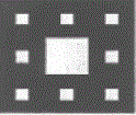
| Sierpinski is designed by dividing normal square patch into nine equal parts and removing centre portion. Normal patch is responsible for lower frequency and slot is responsible for higher frequency. Width and length of simulated sierpinski antenna is 39 and 30 respectively. |
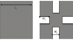
| The Minkowski fractal antenna is designed based on a square generator structure. |
| W1(n+1) = a1xLn |
| W2(n+1) = a2xLn |
| W1 is the middle segment width and W2 the indentation width. a1 is the W1/L0 ratio and a2 is the W2/L0 ratio. n is the iteration number. The initial value of the square length L0=30 mm is found from a typical microstrip patch calculation formula. [7] |
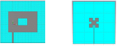
| Figure 4 shows the simulated Sierpinski and minkowski fractal structures. Substrate used for antenna is FR-4 with dielectric constant of 4.2. |
| Frequency, Return loss, Bandwidth and Size of both structures are compared in table 1. |
| Table 1 shows that Simulated sierpinski structure tuned to 2.08GHz and 6.7GHz frequencies .Minkowski structure gave 410MHz and 2.24GHz. For the same dimension (~30mm) minkowski could tuned to 410MHz,but sierpinski tuned only to 2.08GHz. That means for low frequency minkowski is more suited since its dimension is less compared to sierpinski for same frequency.So minkowski fractal structure is selected for proposed antenna. |
SIZE REDUCTION USING FRACTAL STRUCTURE
|
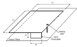
| From different fractal analysis minkowski structure is most suited one when we consider size reduction. By introducing PIFA(Planar Inverted F Antenna) with fractal structure miniaturization is again possible .PIFA can reduce the possible electromagnetic energy absorption by the mobile handset since it have relatively smaller backward radiation toward the user. However, PIFA have some drawbacks such as low efficiency, narrow bandwidth and not multiband. To enhance these drawbacks, especially narrow bandwidth, and to meet the miniaturization requirements of mobile units, Fractal PIFA has been designed[9]. Figure 5 shows PIFA structure. |
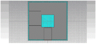
| Sierpinski with PIFA structure is simulated using CST Microwave Studio. Simulated structure is given in Figure 6. |
| Size of a patch antenna is always comparable to quarter wavelength. Maximum size of a patch antenna corresponds to the lowest frequency of multiband antenna. In this case, first GSM Band(800MHz), is the lowest frequency For first GSM Band(800MHz) , dimension is 94mm.That is without PIFA structure, sierpinski fractal have dimension of (~100x100)mm .Using PIFA structure along with sierpinski fractal , the size of the antenna is reduced to (65x65)mm. That means 35% size reduction is possible using PIFA structure. |
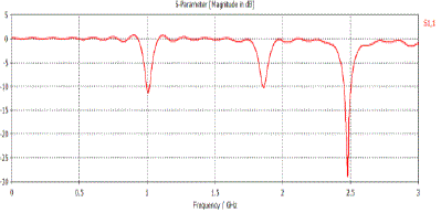
| Return loss of Sierpinski PIFA structure is given in figure 7. |
| From the return loss curve it is clear that required three bands are obtained. The three frequency bands with corresponding bandwidth are given in table 2. |
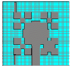
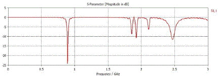
| For Minkowski-PIFA structure ,initial length L0 is 40mm . That is the size of the structure is 40mm and two iterations are done. From this 60% size reduction is possible. Return loss is given in Figure 9. |
| Table 3 shows frequency bands and corresponding bandwidths. |
| All these bands are useful in various wireless applications specifically, Band 1, Band 2,Band 3 for GSM ,Band 4 for 3G services and Band 5 for ISM band. |
CONCLUSION
|
| In this paper analysis different classical fractal structures separately and select minkowski structure which met required frequency bands. Combing fractal structure with PIFA miniaturization is possible. From simulation result it is shown that minkowski second iteration gave more reduced antenna. By combining minkowski with PIFA structure antenna size is again reduced (60% reduction)and which meet required size for wireless communication. |
Tables at a glance
|
|
|
Figures at a glance
|
 |
 |
 |
 |
 |
| Figure 1 |
Figure 2 |
Figure 3 |
Figure 4 |
Figure 5 |
 |
 |
 |
 |
| Figure 5 |
Figure 6 |
Figure 7 |
Figure 9 |
|
References
|
- B. H. Ahmad, H. Nornikman, M. Z. A. Abd Aziz, M. A. Othman, A. R. Othman, "Tri-band Minkowski Island Patch Antenna withComplementary Split Ring Resonator at the Ground Plane’’13th Conference on Microwave Techniques COMITE, 2013, April 17-18,Pardubice, Czech Republic
- Antonio Luiz P. S. Campos and Elder Eldervitch C. de Oliveira,”Design of Miniaturized Frequency Selective Surfaces Using MinkowskiIsland Fractal”, Journal of Microwaves, Optoelectronics and Electromagnetic Applications, Vol. 9, No. 1, June 2010
- Ashutosh Kumar Singh, ReneezAhamadKabeer ,Z.Ali and D.Gurjar,”Performance analysis of compact Koch Fractal antenna at varingiterations”,2013 IEEE
- Federico Viani,”Dual band sierpinskiprefractal antenna for 2.4GHz WLAN and 800MHz LTE wireless Devices”,ProgressInElectromagnetic Research C,Vol.35 ,2013, 63-71
- B. Hephzibah Lincy, A. Srinivasan, B.Rajalakshmi,”Wide Band Fractal Microstrip Antenna For wireless Application”, Proceedings of2013 IEEE Conference on Information and Communication Technologies (lCT 2013)
- M. Dekking, J. L. Vehel, E. Lutton, and C. Tricot (editors), Fractals: Theory and Application in Engineering, Springer-Verlag, London,1999, pp. 125-151
- E.C Lee, P.J Soh, N.B.M Hashim, G.A.E Vandenbosch, V. Volski, I. Adam, H.Mirza,, M.Z.A.A Aziz,”Design and fabrication of flexibleminkowski fractal antenna for VHF application”, Proceedings of the 5th European Conference on Antennas and Propagation (EUCAP)
- Sika Shrestha1, Seung-Jo Han2, Sun-Kuk Noh3, Sunwoong Kim4, Hyun-Bai Kim5, Dong-You Choi” Design of Modified SierpinskiFractal Based Miniaturized Patch Antenna”IEEE 2013
- N. A. Saidatul, A. A. H. Azremi, R. B. Ahmad, P. J. Soh and F. Malek,"Multiband Fractal Planar Inverted F Antenna (F-PIFA) ForMobile phone Application"Progress in electromagnetic reserch B, Vol. 14, 127-148,2009
- K. J. Vinoy, Jose K. Abraham, and Vijay K. Varadan, “On the Relationship Between Fractal Dimension and the Performance of Multi-Resonant Dipole Antennas Using Koch Curves” IEEE transactions on antennas and propagation, vol. 51, no. 9, september 2003
- F. Zubir, M. K. A. Rahim, O. Ayop, A. Wahid,and H. A. Majid,” Design and analysis of microstrip reflect array antenna with minkowskishape radiating element” progress in electromagnetics research b, vol. 24, 317-331, 2010
|