Keywords
|
| Microstrip Antenna, PBG, Transmission Line model, Return Loss |
INTRODUCTION
|
| The widespread adoption of wireless communication was accelerated in the mid 1990s [1]. Microstrip Antennas are widely used in Wireless & Satellite Communication systems because they are low profile, conformable to planar and non planar surfaces, simple and inexpensive to manufacture, mechanically robust, compatible with MMIC designs, and when the particular patch shape and mode are selected, they are very versatile in terms of resonant frequency, polarization, pattern, and impedance [2]. A lot of research is being carried out on Antenna Miniaturization, Bandwidth Enhancement & minimizing return loss. For example, the following antennas have been developed: design of Microstrip Antenna for modern wireless communication [3], design of Microstrip Antenna for GPS application [4], Multiband CPW-fed rectangular ring Microstrip Antenna design for wireless communication [5]. Photonic Band Gap (PBG) or Electromagnetic Band Gap (EBG) materials are periodic dielectrics, which can stop the propagation of electromagnetic waves in certain directions, within certain frequency bands [6]. Several types of PBG or EBG substrates have been investigated [7]. |
| In this paper, a new microstrip antenna for wireless communication usage is presented. The basic element is a square patch. The antenna dimensions are determined to create the required bands resonant frequencies. After determining Antenna parameters, return loss is extracted. Perturbations in form of square slots are introduced on all sides & at centre of the patch. The slots lead to the multiband operation of the antenna. The analysis of the antenna has been done using Zeland IE3D simulation software. The simulated results are presented & discussed. |
CONFIGURATION OF PROPOSED ANTENNA
|
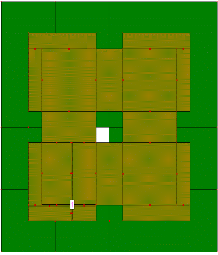
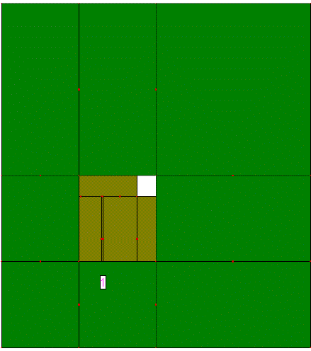
| The geometry of the proposed antenna is shown in figure 1. The square patch has a dimension of 30mm x 30mm. It is printed on a FR4 substrate of thickness 1.6 mm (h) & relative permittivity 4.4 (εr). The patch antenna is coaxially probe fed at (18,12.5).The width (W) & length (L) of patch is calculated using transmission line model equations [2].The patch is perturbed on all sides at the midpoint by 5mm x 5mm. Same perturbation has been created at the centre of patch. Slot has been created in the ground plane leading to formation of PBG which affects the antenna performance significantly. |
SIMULATION RESULTS & DISCUSSION
|
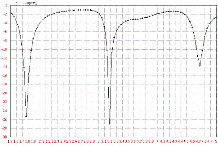
| Return loss is a measure of the effectiveness of power delivery from a transmission line to a load such as an antenna. If the power incident on the antenna-under-test (AUT) is Pin and the power reflected back to the source is Pref, the degree of ref mismatch between the incident and reflected power in the travelling waves is given by the ratio Pin/Pref. The higher this power ratio is, the better the load and line are matched [8]. The return loss of the proposed antenna was found using IE3D simulation software. Simulations show that antenna is having multiband operation with centre frequencies at 1.78 GHz, 3.2 GHz and 4.7 GHz having return loss -25 dB,-27 dB & -14 dB respectively. The corresponding 10 dB return loss bandwidth obtained for the three resonant frequencies are 160 MHz, 90 MHz & 110 MHz respectively. The first frequency band centred at frequency 1.78 GHz covers the GSM frequency band whereas the frequency band with centre frequency of 3.2 GHz is suitable for WiMax operation. The 4.7 GHz frequency band is used is used in defence & for secure communication. |
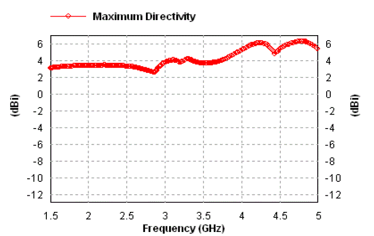
| Directivity is a measure of how 'directional' an antenna's radiation pattern is. Higher directivity implies a more 'focused' or 'directional' antenna. In this case, the Antenna receives 6 times more power in its peak direction than an isotropic antenna would receive. The isotropic antenna is used as a common reference. From the figure, we can see that directivity is between 3.5 & 6 for all frequencies which is in considerable agreement with the typical directivity values of microstrip antenna. |
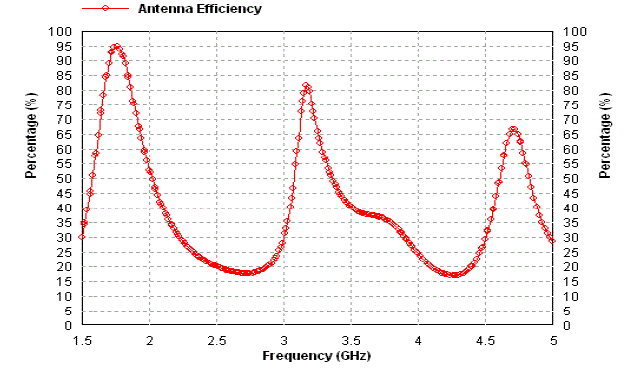
| Antenna Efficiency is defined as "The ratio of the total power radiated by an antenna to the net power accepted by the antenna from the connected transmitter."Generally it is expressed as a percentage (less than 100), and is frequency dependent. The above figure depicts reasonably good antenna efficiency at all the three frequency bands. |
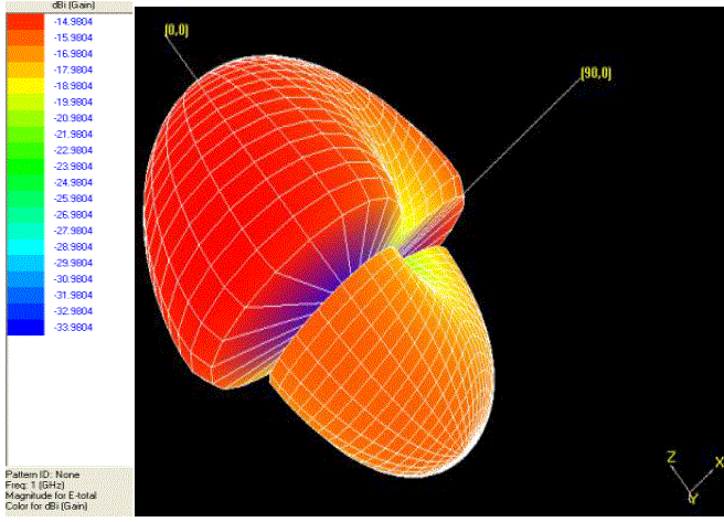
| A radiation pattern defines the variation of the power radiated by an antenna as a function of the direction away from the antenna in antenna’s far-field. The above figure depicts that antenna has good radiating capabilities with a significant main lobe & comparatively smaller sidelobe |
CONCLUSION
|
| A novel microstrip antenna design with perturbations in form of slots has been presented. Simulations show multiband operation with good return loss, directivity & efficiency parameters. The antenna is suitable for GSM, WiMax & Military purposes. |
Tables at a glance
|
 |
| Table 1 |
|
Figures at a glance
|
 |
 |
 |
| Figure 1 |
Figure 2 |
Figure 3 |
 |
 |
 |
| Figure 4 |
Figure 5 |
Figure 6 |
|
References
|
- Ali Foudazi, Hamid Reza Hassani and Sajad Mohammad Ali Nezhad “Small UWB Planar Monopole Antenna with added GPS/GSM/WLANBands,” IEEE transactions on Antenna & Propagation, vol 60, No.6, June 2012.
- C.A. Balanis, Antenna Theory, 2nd ed. New York: John Wiley & Sons, Inc., 1997.
- Thana Pakkiam.K, JS.Mandeep and M.T Islam “ Design of Microstrip Antenna for Modern Wireless Communication” ,1st IEEE InternationalSymposium on Telecommunication Technologies,2012
- Muhammad FadhliBukhori ,NorbahiahMisran,M.T Islam, Mawarni Mohamed Yunus and Mohammed NazmusShakib “ Design of microstripantenna for GPS application”, IEEE international RF & Microwave conference proceedings,2008.
- Emad S. Ahmed “Multiband CPW-fed rectangular ring Microstrip Antenna design for Wireless Communications” 2011 IEEE JordanConference on Applied Electrical Engineering & Computing Technologies.
- R. Gonzalo, P. De Maagt, and M. Sorolla, “Enhanced patch-antenna performance by suppressing surface waves using photonic band gapSubstrates,” IEEE Trans. Microwave Theory Tech., vol. 47, pp2131–2138, Nov. 1999
- Rahman, M., and Stuchly, M.A.: “Wide-band microstrip patch antenna with planar PBG structure” Proc. IEEE Symp. on Antennas andPropagation, 8–13 July 2001, Vol. 2, pp. 486–489
- Trevor S. Bird,”Definition& Misuse of Return Loss”IEEE Antennas &Propogation Magazine” April 2009
|