Keywords
|
| MC-CDMA, CI codes |
INTRODUCTION
|
| In multicode CDMA, well known orthogonal Walsh- Hadamard (WH) codes are used to assign multiple codes. But WH codes exist for certain code length (2p, p ∈I+). So, in cognitive radio and/or dynamic spectrum access, WH code sets need to deactivate more number of subcarrier. Recently Liet al. proposed a novel spreading code called orthogonal binary code (based on WH code) of any code length to increase diversity gain. Carrier interferometry(CI) codes (complex orthogonal spreading codes) have unique features which allow MC-CDMA to: 1) have orthogonal spreading sequence of any length N, (N ∈I+), 2) support additional (N − 1) pulse shape (with πN phase shifted) to accommodate extra users or information using pseudo-orthogonal CI (POCI) codes with no expansion in bandwidth. The use of carrier interferometry (CI) codes further improves user capacity relative to the conventional spreading code. Multicarrier code division multiple access (MCCDMA) represents a combination of two techniques, namely OFDM (orthogonal frequency division multiplexing) and CDMA (code division multiple access). |
| Code Division Multiple Access (CDMA) technology is a continuing driving force behind wireless networks around the globe and according to the CDMA Development Group (CDG), there were 431 million CDMA subscribers and 91million CDMA 2000 1x subscribers worldwide by the end of the year 2007. Multi-Carrier Code Division Multiple Access (MCCDMA) is a multiple access scheme used in MCCDMA-based telecommunication systems, allowing the system to support multiple users at the same time. |
| Multicarrier code division multiple access (MC-CDMA) [1] has emerged as a powerful alternative to conventional direct sequence CDMA (DS-CDMA) [2] in mobile wireless communications. In MC-CDMA, each user’s data symbol is transmitted simultaneously over narrow-band sub- carriers, with each subcarrier encoded with a 1 or 1 (as determined by an assigned spreading code). Multiple users are assigned unique, orthogonal (or pseudo-orthogonal) codes. |
| In fixed spreading gain, low data rate users suffer from more multiple access interference (MAI) than high data rate users because high data rate users transmit larger amount of time. In variable spreading gain (VSG), inter symbol interference (ISI) is one of the drawbacks for high data rate users due to short spreading gain over multipath channel. To support time varying quality of service (QoS) with multicarrier code division multiple access (MC-CDMA), different techniques have been developed earlier [1], [2]. The presence of distinct peaks and nulls in the interference patterns has motivated the widespread use of interferometry. The ideas underlying interferometry lend themselves naturally to multiple access applications in telecommunications. For multi-rate transmissions, Multi-Code (MC) and Variable-Spreading-Length (VSL) are two widely adopted multi-rate schemes in CDMA system, and their applications in MC-CDMA were studied with LMMSE MUD effectively to mitigate multiple access. |
| 1. MCCDMA transmission |
| This section describes the model of CI/MC-CDMA system considered in the paper. Synchronous CI/MC- CDMA system with K users is considered. Each user employs N subcarriers with binary phase-shift keying (BPSK) modulation. CI code [21,22] of length N for kth user (1 ≥ k ≥ K). |
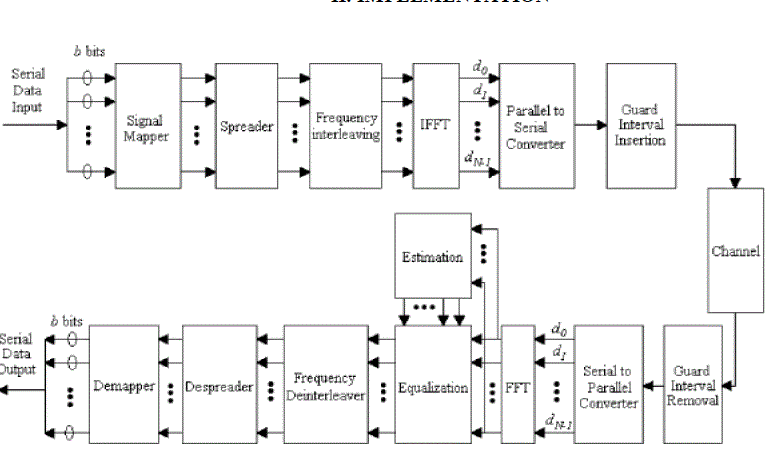
Signal generation: An ideal MCCDMA signal, could be generated by a bank of oscillators. Such an implementation could, however, become prohibitively complex as the number of subcarriers becomes large. Similar to the demodulation of the data samples with the DFT, the baseband signal can be generated digitally by means of an IDFT. Figure 1 shows such an MCCDMA transmitter. This has paved the way for practical use of MCCDMA. Consider the signal  for all t, (1) Where for all t, (1) Where |
 ,n = 0,…. , lN − 1(2) is the oversampled IDFT of the constellation symbols xk, the integer l ≥ 1, and g(t) is an interpolating filter. The output signal from the D/As??(t), can be made very close to the ideal signal s(t) as defined in (2). The quality of the approximation depends on, for example, the characteristics of the D/A including the interpolation filter and the IDFT. ,n = 0,…. , lN − 1(2) is the oversampled IDFT of the constellation symbols xk, the integer l ≥ 1, and g(t) is an interpolating filter. The output signal from the D/As??(t), can be made very close to the ideal signal s(t) as defined in (2). The quality of the approximation depends on, for example, the characteristics of the D/A including the interpolation filter and the IDFT. |
| The spectrum decays with 1/f and spectral leakage into neighbouring bands is sometimes too large to meet regulation requirements. Several approaches have been taken to combat this out-of-band emission. The most straightforward is perhaps to use a large number of subcarriers to narrow the spectra, however at the cost of increased complexity, increased sensitivity to Doppler effects, and higher demands on the accuracy of frequency synchronization. |
| Another approach is to use pulse shaping of the MCCDMA symbol to change the spectral occupancy. Pulse shaping can be done either by applying a time window to the MCCDMA symbol or by passing the MCCDMA signal through a filter, typically combined with the interpolation filter above. Pulse shaping has to be applied with care since orthogonality between the subcarriers is rarely maintained. |
| Compared with the rectangular window, the symbol has been cyclically extended with a number of extra samples shaped with a raised cosine window. |
| Whereas the application of pulse shaping can improve the spectral occupancy of an MCCDMA system, its effect on other system characteristics has also motivated some recent studies towards design of suitable pulse shapes. Much of this work focuses on the choice of new sets of basis functions for the modulation of parallel channels and on how such pulses improve an MCCDMA system’s robustness to Doppler effects, carrier frequency variations, and time synchronization. The application of wavelet theory to multicarrier communications and pulse shaping is documented. |
| 2. Iterative interference cancellation receiver |
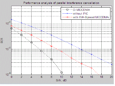
| In this section, conventional PIC structure is discussed. The estimated interference due to (K - 1) users is directly subtracted from r(t) for the desired kth user. The improved received signal rkiter(t) of kth user may be written as |
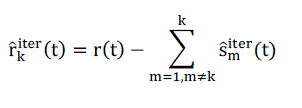 (3) (3) |
| Where smiter (t) is the estimated signal at iter-th iteration for the mth user smiter(t) can be written as, |
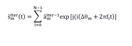 |
| 3.MCCDMA reception |
| In Section II we have discussed aspects of the demodulation of data in MCCDMA. Two other important parts of the processing of the received MCCDMA signal are synchronization and channel estimation. Here we address these topics. |
| Synchronization :At the front-end of the receiver MCCDMA signals are subject to synchronization errors due to oscillator impairments and sample clock differences. The demodulation of the received radio signal to baseband, possibly via an intermediate frequency, involves oscillators whose frequencies may not be perfectly aligned with the transmitter frequencies. This results in a carrier frequency offset. Figure 1 illustrates the front end of an MCCDMA receiver where these errors can occur. Also, demodulation (in particular the radio frequency demodulation) usually introduces phase noise acting as an unwanted phase modulation of the carrier wave. Carrier frequency offset and phase noise degrades the performance of an MCCDMA system. |
| When the baseband signal is sampled at the A/D, the sample clock frequency at the receiver may not be the same as that at the transmitter. Not only may this sample clock offset cause errors, it may also cause the duration of an MCCDMA symbol at the receiver to be different from that at the transmitter. If the symbol clock is derived from the sample clock this generates variations in the symbol clock. Since the receiver needs to determine when the MCCDMA symbol begins for proper demodulation with the FFT, a symbol synchronization algorithm at the receiver is usually necessary. Symbol synchronization also compensates for delay changes in the channel. |
III. DESIGN OF MCCDMA SIGNALS
|
| The number of subcarriers N, the bandwidth of each subcarrier 1/NT, the bandwidth of the system B ≈ 1/T, and the length of the cyclic prefix Δ are all important parameters in the design of an MCCDMA system. |
| First, the length of the cyclic prefix should be chosen to be a small fraction of the MCCDMA symbol length to minimize the loss of SNR (or data rate) in (9). Because the size of the cyclic prefix is directly related to the delay spread of the channel a rule of thumb is that the length of the MCCDMA symbol NT ?? τ or, equivalently, the number of subcarriers N>>τB. However, if the MCCDMA symbol length NT is too long the ICI caused by Doppler spreading in the fading channel can become performance limiting. If the inter carrier spacing 1/NT is chosen much larger than the maximum Doppler frequency fd, the system is relatively insensitive to the Doppler spread and the associated ICI. Therefore, the number of subcarriers should satisfy fd<< 1/NT or equivalently N<<B/fd. The above two constraints result in the following restriction on the number of subcarriers |
| τB << N<< B/fd (5) |
| Eqn (3) also states a requirement on the delay- and Doppler-spread of the physical channel for proper design of an MCCDMA system. The far left hand side and the far right hand side also lead to fdτ<<1, which means that the more the channel is under spread, i.e., the more correlated the channel is in either time or frequency, the easier it is to find a suitable number of subcarriers N.A typical UMTS radio interface thus could use 1024 subcarriers implemented with an 1024-point FFT. |
| The length of the cyclic prefix must be larger than the channel impulse response, that is Δ >10μsec. A possible design example of a 64-sample cyclic prefix (12.8 μsec) leads to a reduction of the data rate and transmission power of 6%. If we modulate each subcarrier with a QPSK symbol, we have b = 2 bits per subcarrier giving us an overall raw data rate of 9.4 Mbits/sec. Similarly, an extension to 16-QAM symbols would give 18.8 Mbits/sec raw data rate. |
V. CONCLUSIONS
|
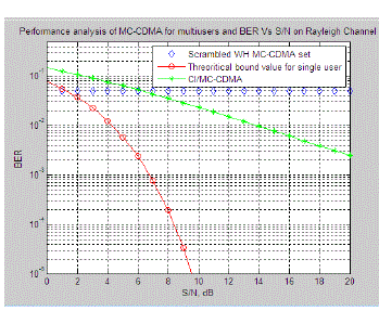
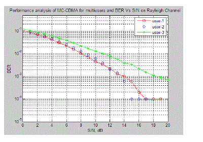
| In this paper, we analyze the performance of multirate multicarrier code division multiple access (MC-CDMA) using carrier interferometry(CI) codes. Initially we analyzes the MC-CDMA multiple access scheme with various user data rate.We illustrated the performance of numerical simulations, and it shows a significant BER performance improvement for different users, while reducing the complexity of the receiver architecture in real time. |
Figures at a glance
|
 |
 |
 |
 |
| Figure 1 |
Figure 2 |
Figure 3 |
Figure 4 |
|
| |
References
|
- Cottatellucci L, Muller R. R. and Oebbah M, 2001, Asynchronous CDMA System with Random Spreading - Part I : Fundamental Limits, IEEE Transactions on Information Theory, Volume : 56, Issue : 4, PP 1477-1497.
- G. L and Feher K. , 2004, Efficient Filter Oesign for IS-95 CDMA Systems, IEEE Transactions on Consumer Electronics, Volume: 42, Issue: 4 PP 10 11 - 1020.
- UuanbinGuo, Dennis McCain and Joseph R C avallaro, 2004, Low Complexity System-on-Chip Architecture of Parallel Compensation in CDMA Systems, ISCAS, PP : IV 77 – 80
- Boukadourn M. ,Tabari K. , Bensaoula A, Starikov o. and Aboulhanid E. M. , 2005, FPGA Implementation of a CDMA Source Coding and Modulation Subsystem for a Multiband Fluorometer with Pattern Recognition C apabilities, IEEE International Symposium on Circuits and Systems,Volume : 5, PP 4767 - 4770.
- Magaa, ME, Rajatasereekul, T., Hank, D. and Hsiao-Hwa Chen, 2007, Design of an MC-CDMA System That Uses Complete Complementary Orthogonal Spreading Codes", IEEE Transactions on Vehicular Technology, Volume: 56, Issue: 5, PP: 2976 - 2989.
- Clarke P. and de Lamare R. C, 2010, Low-Complexity Reduced-Rank Linear Interference Suppression Based on Set-Membership Joint Iterative Optimization for OS-CDMA Systems, IEEE Transactions on Vehicular Technology, Volume : 60, Issue : 9, PP 4324 - 4337.
- Theodore S Rappaport, 2010, "Wireless Communication – Principles and Practices", 2ND Edition, Pearson Education, Dorling Kindersley (India) Pvt Ltd.
- Min Shi D'Amours, C. Yongacoglu, A. 2010, Design of spreading permutations for MIMO-CDMA based on space-time block codes, Communications Letters, IEEE, Volume: 14 Issue: 1, PP: 36 - 38 .
- VishwasSundaramurthy and Joseph C avallaro, 2011, A Software Simulation Testbed for Third Generation COMA Wireless Systems, Proc. 33,dAsilomarConf on Signals, Systems and Computers, Pacific Grove C A.
|