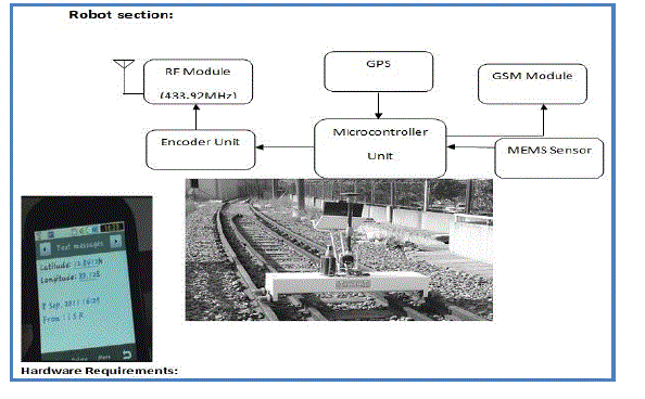
This project is a cost effective yet vigorous solution to the problem of railway track geometry survey utilizing a method that is unique in the sense that while it is simple, the idea is completely novel and up till now untested. The project discusses the technical and design aspects in detail and also provides the proposed multi sensor railway track geometry surveying system. This project also presents the details of the implementation results of utilizing simple components inclusive of a GPS module, GSM Modem and MEMS based track detector assembly. In railway bridges, any time the bridge it’s striking due to weather condition, floods, earthquake, cyclone, etc. Now days system have some limitations, if the bridge or track damaged, that information goes to railway authority people, they notifies and informs to the corresponding trains it will takes more time informing those information. So to avoid delays, our proposed system will immediately notifies and informs the current train comes on the track through wireless medium. Bridge damage status is monitored by the Ultrasonic sensor and wireless modules, when the sensor not getting signal, immediately nearby wireless system notifies and alert or informs to the current train on the track. The above task can achieve through microcontrollers, GSM, MEMS. The same information can be passed to all trains coming on the track.
Keywords |
| Data fusion, MEMS and ultrasonic (US) sensors, sensor-emission encoding, validation of obstacle
detection |
INTRODUCTION |
| IN ALL transport systems, particularly in the case of railways, safety and reliability are highly considered [1].
Because of the constant need to improve railway safety, the existence of objects on the tracks is considered. On non
high-speed lines (standard lines), there exist critical areas where it is necessary to detect the presence of obstacles: the
level or grade crossings. A comparatively high amount of dedicated sensory systems has been installed in areas at or
near level crossings to prevent collisions between trains and vehicles. In [2], there is recent analysis about the
phenomena that may cause collisions at level crossings. On high-speed lines, there are no level crossings, but zones
close to bridges or tunnels are considered to be quite critical since objects can fall on to the tracks. This can be caused
by the fall of a vehicle, or a material being transported by a vehicle, onto the line. Landslides can also happen at the
entrances and exits of tunnels. In these critical areas, if there is a system to detect the presence of obstacles [3], railway
traffic can be halted, and possible accidents can be avoided. These systems sometimes generate false alarms, thus
creating financial losses whenever the system detects an obstacle that does not actually exist. To avoid the generation of
false alarms, it has become necessary to increase the reliability of the detection system. Reliability is highly influenced
by the design of the sensor used, the conditions in which the sensor is working, and the signal processing that is carried
out by the system. This paper focuses on one of such systems to detect obstacles on high-speed lines in a reliable way. |
| In adverse environments, there may be chances for producing false alarms. It may be due to weather conditions or
solar radiations. Due to the fact that the ideal sensor does not exist [5], in this paper, a multisensory system is proposed
so that the drawbacks of using any particular type of sensor are outweighed by the performance characteristics of the
other types of sensors. |
| The proposal is based on the barrier consisting of infrared proximity sensor and ultrasonic sensor. The reliability of
the detection system is improved in three ways. First, a robust codification scheme based on mutually orthogonal
complementary sets of sequences is proposed. It simultaneously provides multiple emissions and multiple receptions,
avoids interference among the emissions, and can function with a low signal-to-noise ratio. Second, the use of fuzzy
logic to combine the information given by the two sensors (IR Proximity and US) is proposed. Finally, the fusion of
this information by means of the Dempster–Shafer evidential theory [6] is proposed to obtain a certainty value for the
existence of objects (greater than 50 × 50 × 50 cm), which may pose a risk to railway traffic. |
II. DESIGNED SENSORY SYSTEM |
A. Detection System |
| The designed sensory system is composed of two multisensory barriers, i.e., one emitting and the other
receiving, which are placed at both sides of the railway. The minimum dimensions of the object to be detected are 50 ×
50 × 50 cm, whereas the distance between contiguous transducers is 25 cm. As a result, if an object with minimum
dimensions is in the scanned area, at least two links are interrupted. The distance between emitters and receivers is 14
m, given the width of the railway line, although the distance between emitters and receivers may be sometimes greater.
The required scan time is 500 ms, and if an obstacle is inside the detection area for more than 3 s, an alarm must be
generated. |
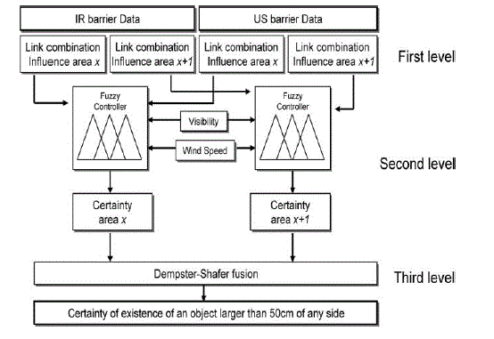
| Fig. 1 shows a proposal for an obstacle-detection system. It is divided into three processing levels: 1) the sensory
modules (the multisensory barrier); 2) the individual process units; and 3) an integration module for obstacle detection
and location. An IR emitter with an aperture angle of +2◦, at a distance of 14 m from a receiving barrier, can send
emissions to up to five receivers, thus establishing five connections per emitter. In the case of US emitters, the aperture
angle is higher; however, to have the same links and similar information in both barriers, only five links are taken into
account. Due to the fact that the detection is based on link interruptions, if a sensor is not working, it could be
mistaken for obstacle detection. Nevertheless, the number of interrupted links allows the system to distinguish the
presence of an obstacle from a sensor that is out of order, this being of particular advantage for maintenance tasks. |
B. Emission Encoding |
| Since a multimode operation is carried out in the barrier [8] (simultaneous multi emission and multi reception), it is
necessary to encode every emission to avoid interferences among the different emissions and to discriminate them at
the receiving block. For that reason, mutually orthogonal complementary sets of sequences have been used [9]. More
details about the encoding scheme and the adaptation of the different sensors can be found in [7]. False alarms can be
reduced using a dynamic threshold that it is dynamically adapted by considering meteorology and solar interference. |
III. OBJECT VALIDATION |
| It is necessary to combine data from different sources, taking into account external variables such as weather
conditions or sensor degradation. For the IR barrier, weather conditions can be modeled by considering visibility [10],
[11]. There is a direct relation between visibility and atmospheric attenuation. For the US barrier, the main factor that
can influence its performance is the level of turbulence, and to assess the effect of such turbulence, it is necessary to
measure the wind speed [4]. The data fusion has been carried out at three levels. Fig. 2 shows the data fusion
architecture carried out for two consecutive influence areas. First, the detection area for each barrier has been divided
into 25-cm-wide influence areas according to the receivers; therefore, if a dangerous object exists, it is detected in two
consecutive influence areas. The result of this level is a measurement of the certainty of existence of objects in every
influence area. Second, a fuzzy controller (the fuzzy controller theory can be found in [12]) has been included to weigh
up the certainty of existence of objects in every influence area, taking into account the information given by the two
barriers and the visibility and wind-speed values. As a result, by fusing the information from the two barriers, a final
value for the certainty of existence of objects in every influence area can be obtained. Finally, values for the certainty
of the existence of objects belonging to two consecutive influence areas have been fused by means of the Dempster–
Shafer evidential theory [13], [14] to obtain a final value for the certainty of existence of objects larger than 50 × 50 ×
50 cm. |
| The first level is the Certainty of Existence of Objects in the Influence Area. Second level is the Fuzzy Controller.
Third level is the Dempter - Shafter theory application. If there is a movement of any small animals or some other
unwanted factors may produce false alarms. By using Fuzzy Controller and the Dempter – Shafter theory this
disadvantage is eliminated. Since the Fuzzy Controller give intermediate values, the Dempter – Shafter theory is used
to produce accurate values. The accurate values are produced by the combination of several values from the Infrared
proximity and Ultrasonic sensors. |
A. First Level. The Certainty of Existence of Objects in the Influence Area |
| The influence area is analysed and the value for the certainty of the existence of the objects is analysed. For each
influence area several links exist. These links occur between multiple emitter and multiple receiver. If any link is interrupted in a particular area then the probability of the object to be in that area depends on the percentage of the
range of the link that is placed in that particular area. To determine the link that is interrupted, the state is evaluated
whether its ON or OFF state. |
B. Second Level. Fuzzy Controller |
| After the certainties of existence of objects for every zone and each barrier are available, it is necessary to combine
them to have only one certainty value for every zone. Fuzzy logic introduces a concept of partial truth values that lie in
between “completely true” and “completely false.” The central concept of fuzzy logic is the membership function,
which numerically represents the degree of belonging of an element to a set. An element can be a member of a set at a
certain degree and be a member of a different set at the same time. The proposal is to use a Mamdani fuzzy controller
[15], which models the outputs using fuzzy sets that are easy to design. The design of the Fuzzy Controller includes
some steps. |
| 1) Data Inputs: The fuzzy controller data inputs consist of the following sources of information. Certainty of the
existence of objects for each barrier. The certainty of the existence of an object is calculated for both Infrared Proximity
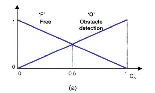
sensors and Ultrasonic sensors. The degree of confidence about the existence of object, taking values from zero (tracks
free of objects) to one (an obstacle exists). Two fuzzy sets (F “Free” and O “Obstacle detection”) are defined to indicate
the state of the link [Fig. 3(a). Wind - speed measurement. |
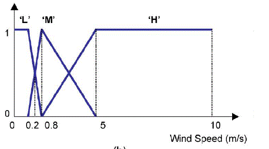
| Wind speed has been considered from 0 to 10.5 m/s, as shown in Fig. 3(b). A wind speed that is higher than 10.5 m/s
produces turbulences, causing the coherence time to be under the emission time; therefore, the emission becomes
unrecognizable for the receiver. Three fuzzy sets (L, M, and H) are defined, and their limits are set in function of the
above-commented turbulence influence on the US barrier. |
Visibility conditions. |
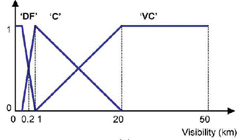
| The confidence level of the IR barrier is adjusted according to the visibility conditions. Visibility takes values from
50 km (for very clear days) to 50 m (dense fog). Three fuzzy sets are defined (DF, C, and VC), and their limits are
experimentally adjusted by using the IR barrier performance [Fig. 3(c)] [10]. |
2) Data Outputs: |
| The fuzzy controller output is the modified certainty of existence of an object in the area under supervision, including
the environmental effects three fuzzy sets are defined (F, O, and I). Its range takes values from zero (free of obstacles)
to one (obstacle detection). The I fuzzy set is added to model the situation when the correlation values are very low
(which means that obstacles can exist); however, the weather conditions invalidate the measurements (high wind speed
or very low visibility). |
3) Rule definition and the defuzzification process: |
| Finally, a set of rules is necessary to transform the variables into a fuzzy result. The knowledge is typically
represented in terms of if–then rules. An example is as follows: Take A and B, then C. The if-part of the rule is called
the premise, and the then part is called the consequent. The truth value of the rule’s premise describes to what degree
the rule applies in a given situation. The so-called fuzzy inference mechanism is used to determine the consequent
fuzzy set based on the truth value of the premise Consequent fuzzy sets of individual rules are then combined
(aggregated) into a single fuzzy set. The resulting fuzzy set is converted (de fuzzified) into a real (crisp) value, in this
case indicating the fuzzy certainty of existence of objects CA. |
| The operators that have to be defined in a fuzzy controller describe the operations between rules, in other words, the
“and” connector, which is defined as the “minimum” operation, the “or” connector, which is defined as the “maximum”
operation, and the “aggregation” of the different rules that are involved in the fusion process that is defined as the
“maximum” operation. Since the controller is modeled as a Mamdani controller, a defuzzification process is necessary
to obtain a quantifiable result in the fuzzy logic, as opposed to the Sugeno controller that uses numeric rules to obtain the output. There are several methods to transform the fuzzy outputs into a numerical value, which can be used by the
next fusion step. The one used in this paper is the center of-area (CoA) method [16], [17]. The CoA method calculates
the center of gravity of the final fuzzy control space, producing a result that is sensitive to all rules. |
C. Third Level. The Dempster–Shafer Theory Application |
| After the values for the certainty of existence of objects are available for every area, they can be combined between
consecutive areas to obtain the certainty of existence of objects larger than 50 × 50 × 50 cm. It is proposed to use the
Dempster–Shafer evidential theory [14]. This probability-based data fusion classification algorithm is useful when the
information sources contributing data cannot associate a 100% probability of certainty to their output decisions. In this
theory, each information source associates a declaration or hypothesis with a probability mass, expressing the amount
of support or belief directly attributed to the declaration, in other words, the certainty of the declaration. The probability
masses for the decisions made by each information source are then combined by using Dempster’s rule of combination.
The hypothesis favored by the largest accumulation of evidence from all the information sources is selected as the most
probable outcome of the fusion process. The Dempster–Shafer theory estimates how close the evidence is to forcing the
truth of a hypothesis, rather than estimating how close the hypothesis is to be being true. |
IV. RESULT |
| Results have concluded that the encoding scheme can cope with signal-to-noise ratios that are lower than −10 dB. For
the Ultrasonic, there exist objects (mainly because one emitter is not working). However, the algorithm filters those
situations where there are several small objects, or a sensor in a barrier is off due to the fact that the corresponding
sensor in the other barrier is working properly. If two sensors, i.e., one in each barrier, occupying the same position are
simultaneously off, the algorithm considers that there is a small object since only one influence area is affected, but the
alarm is not generated. Railway Regulations required a scan time of 500 ms, and if an obstacle is inside the detection
area for more than 3 s, an alarm must be generated. The information is sent as Short Message Service as an indication
by using GPs and GSM. In that time, this system can give almost 30 measurements about the state of the tracks using
two different technologies. Therefore, reliable information can be provided for safe train circulation. |
V. CONCLUSION |
| A proposal of a multisensory system for obstacle detection on railways has been proposed, based on
the complementary use of MEMS and US barriers, achieving high reliability. In this paper, apart from the use of two
different sensor technologies, the reliability of the detection system has been increased due to the following reasons.
First, a robust encoding scheme based on mutually orthogonal complementary sets of sequences has been implemented.
It provides multi emission and multi reception, avoids interferences among the emissions, and can cope with low
signal-to-noise ratios. Second, a fuzzy controller has been included to combine the information given by the two
sensors (MEMS and US). It generates a value for the certainty of the existence of objects considering some external
agents, such as visibility and wind speed that can affect the sensor measurements. In this project discusses the technical
and design aspects in detail and also provides the proposed multi sensor railway track geometry surveying system. This
project also presents the details of the implementation results of utilizing simple components inclusive of a GPS
module, GSM Modem and MEMS based track detector assembly. |
Figures at a glance |
 |
 |
 |
 |
 |
| Figure 1 |
Figure 2 |
Figure 3a |
Figure 3b |
Figure 3c |
|
| |
References |
- M. Arai, âÃâ¬ÃÅRailway safety for the 21st century,âÃâ¬Ã Jpn. Railway Transp. Rev., vol. 36, pp. 42âÃâ¬Ãâ47, Sep. 2003.
- M. Ghazel, âÃâ¬ÃÅUsing stochastic Petri nets for level crossing collision risk assessment,âÃâ¬Ã IEEE Trans. Intell. Transp. Syst., vol. 10, no. 4, pp. 668âÃâ¬Ãâ 677, Dec. 2009, Digital Object Identifier 10.1109/TITS.2009.2026310.
- K. Krishnaswami and M. Tilleman, âÃâ¬ÃÅOff the line-of sight laser radar,âÃâ¬Ã Appl. Opt., vol. 37, no. 3, pp. 565âÃâ¬Ãâ572, Jan. 1998.
- F. J. ÃÆÃÂlvarez, J. UreÃÆña, A. HernÃÆández, M. Mazo, J. J. GarcÃÆÃÂa, and A. JimÃÆénez, âÃâ¬ÃÅInfluence of atmospheric refraction on the performance of an outdoor ultrasonic pulse compression system,âÃâ¬Ã Appl. Acoust., vol. 69, no. 11, pp. 994âÃâ¬Ãâ1002, Sep. 2007.
- Y. Ruichek, âÃâ¬ÃÅMultilevel- and neural-network-based stereo-matching method for real-time obstacle detection using linear cameras,âÃâ¬Ã IEEE Trans.Intell. Transp. Syst., vol. 6, no. 1, pp. 54âÃâ¬Ãâ62, Mar. 2005.
- Y. Chen, Q.-J.Kong, Y. Liu, and Z. Li, âÃâ¬ÃÅAn approach to urban traffic state estimation by fusing multisource information,âÃâ¬Ã IEEE Trans. Intell. Transp. Syst., vol. 10, no. 3, pp. 499âÃâ¬Ãâ511, Sep. 2009.
- M. J. DÃÆÃÂaz, J. J. GarcÃÆÃÂa, ÃÆÃÂ. HernÃÆández, C. Losada, and E. GarcÃÆÃÂa, âÃâ¬ÃÅAdvanced multisensorial barrier for obstacle detection ,âÃâ¬Ã in Proc. IEEE Int. Symp. WISP, Madrid, Spain, 2007, pp. 549âÃâ¬Ãâ554.
- J. J. GarcÃÆÃÂa, C. Losada, F. Espinosa, J. UreÃÆña, ÃÆÃÂ. HernÃÆández, M. Mazo, C. de Marziani, A. JimÃÆénez, F. ÃÆÃÂlvarez, and J. A. JimÃÆénez, âÃâ¬ÃÅOptimal estimation techniques to reduce false alarms in railway obstacle detection,âÃâ¬Ã in Proc. IEEE ICIT, Hong Kong, 2005, pp. 459âÃâ¬Ãâ464.
- A. Chow, âÃâ¬ÃÅPerformance of spreading Codes for direct sequence code division multiple access (DS-CDMA),âÃâ¬Ã Stanford Univ., Stanford, CA, Dec.5, 2003.
- S. Bloom, E. Korevaar, J. Schuster, and H. Willebrand, âÃâ¬ÃÅUnderstanding the performance of free-space optics [Invited],âÃâ¬Ã J. Opt. Netw., vol. 2, no.6, pp. 178âÃâ¬Ãâ200, Jun. 2003.
- N. Hautiere, R. Labayrade, and D. Aubert, âÃâ¬ÃÅReal-time disparity contrast combination for onboard estimation of the visibility distance,âÃâ¬Ã IEEE Trans. Intell. Transp. Syst., vol. 7, no. 2, pp. 201âÃâ¬Ãâ212, Jun. 2006.
- H. Ying, Fuzzy Control and Modeling: Analytical Foundations and Applications. New York: Wiley-IEEE Press, Aug. 2000.
- L. A. Klein, Data and Sensor Fusion: A Tool for Information Assessment and Decision Making. Bellingham, WA: SPIE, 2004.
- G. Shafer, AMathematical Theory of Evidence. Princeton, NJ: Princeton Univ. Press, 1976.
- E. H. Mamdani and S. Assilian, âÃâ¬ÃÅAn experiment in linguistic synthesis with a fuzzy logic controller,âÃâ¬Ã Int. J. Man-Mach. Stud., vol. 7, no. 1, pp.1âÃâ¬Ãâ13, Jan. 1975.
- J. E. Naranjo, C. Gonzalez, R. Garcia, and T. de Pedro, âÃâ¬ÃÅLane-change fuzzy control in autonomous vehicles for the overtaking maneuver,âÃâ¬Ã IEEETrans. Intell. Transp. Syst., vol. 9, no. 3, pp. 438âÃâ¬Ãâ450, Sep. 2008.
- K. M. Passino and S. Yurkovich, Fuzzy Control. Reading, MA: Addison- Wesley, 1998.
|